¶ DAMPER SECTION AND END PANEL
¶ IDENTIFICATION, ASSEMBLY AND INSTALLATION
The damper section or end panel contains louvre dampers.
If included in the scope of supply, the damper actuator may be factory-fitted on request. Otherwise, the recommended installation procedure is specified in Section 5.28 ACTUATOR INSTALLATION. The electrical wiring of the actuators is specified in the “Installation and Operation Manual for the Measurement and Regulation System”.
The damper section or end panel is fitted with louvre dampers as standard at the factory.
The dampers may be located inside or outside the section.
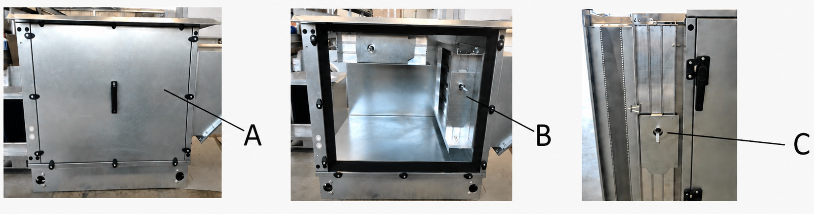
Access to the dampers is shown in the following figure:
A
Service panel of the damper section/internal dampers of the end panel
The panel can be removed using a 5.0 mm Allen key
B
Internal space of the section
Internal dampers with brackets for actuator installation
C
External damper of the end panel
Dampers with a bracket for actuator installation
¶ COMMISSIONING
¶ TASKS BEFORE COMMISSIONING
| __________________ | __________________ | ||
|---|---|---|---|
| Order number: | User: | ||
| Date: | Commissioning engineer: | ||
| Project name: | |||
| Serial number: | |||
| Address: | |||
| Initial start-up date: | Position: |
Tasks for damper sections and end panels
| Number | Description of service task | Task performed | Measured or set value | Note | |
|---|---|---|---|---|---|
| YES | NO | ||||
| 1.01 | Check the position of the dampers according to the technical specification of the unit – internal/external. | ||||
| 1.02 | Check that the dampers are secured to the supporting structure. | ||||
| 1.03 | Check that the dampers rotate freely. | ||||
| 1.04 | Check that the dampers close completely. | ||||
| 1.05 | |||||
| 1.06 | |||||
| 1.07 | |||||
| 1.08 | |||||
| 1.09 | |||||
| 1.10 | |||||
| 1.11 | |||||
| 1.12 | |||||
| 1.13 | |||||
| 1.14 | |||||
| 1.15 | |||||
| 1.16 | |||||
| 1.17 |
Tasks for damper sections and end panels – measurement and regulation system
| Number | Description of service task | Task performed | Measured or set value | Note | |
|---|---|---|---|---|---|
| YES | NO | ||||
| 1.18 | Check the installation and wiring of the actuators in accordance with the installation instructions. | ||||
| 1.19 | |||||
| 1.20 | |||||
| 1.21 | |||||
| 1.22 | |||||
| 1.23 | |||||
| 1.24 | |||||
| 1.25 |
Special tasks:
| Number | Description of service task | Task performed | Measured or set value | Note | |
|---|---|---|---|---|---|
| YES | NO | ||||
| 1.20 | |||||
| 1.21 | |||||
| 1.22 |
| At....................on.................... | |||
| ______________________ | ______________________ | ||
| Stamp and signature of the service technician: | Stamp and signature of the authorised representative of the equipment operator | ||
| ______________________ | ______________________ | ||
| Surname and number of the service technician Surname of the authorised representative of the operator in block letters | Surname of the authorised representative of the operator in block letters. |
*Enter a value only when a quantity must be measured.
¶ COMMISSIONING TASKS
¶ TASKS DURING INITIAL START-UP
During initial start-up, the following in particular must be checked:
Damper section and end panels:
• Correct direction of damper rotation; if necessary, change the actuator switch setting; see Section 5.28 ACTUATOR INSTALLATION
¶ OPERATION AND MAINTENANCE
Detailed operating instructions and maintenance and service procedures are provided in the following sections and in the sections covering the individual parts of the unit.
The blades of an open damper must be secured against spontaneous or accidental closing. Never place limbs between the blades of an open damper, as this may cause serious injury!
Check for contamination and possible damage, the free movement of the damper blades and, in particular, correct damper closure. Remove any dust deposits with a vacuum cleaner; the surfaces of the damper blades may then also be cleaned with a damp cloth. The plastic damper gears are made of a material that does not require additional lubrication. For dampers with a linkage mechanism, lubricate the necessary points of the lever mechanism with a lubricating spray. If a flexible connection is installed downstream of the damper, check its tightness and integrity and clean it if necessary.
¶ SERVICE AND MAINTENANCE INTERVALS
| SERVICE AND MAINTENANCE TASKS | ||||||||
|---|---|---|---|---|---|---|---|---|
| Inspection task | Unit in operation Y/N* | Service/remedial action | Intervals (months) | |||||
| END DAMPERS, DAMPER SECTION AND END-PANEL DAMPER | 1 | 3 | 6 | 12 | ||||
| 01. | Check the free movement of the dampers. | N | repair/replacement | ✓ | ||||
| 02. | Check the dampers for contamination. | N | cleaning | ✓ |
* operating status of the unit during the inspection