¶ LIQUID CIRCUIT CHAMBERS - HEAT RECOVERY
¶ IDENTIFICATION, ASSEMBLY AND INSTALLATION
The chambers are manufactured as standard as a water heater chamber and a water cooler chamber. The same installation requirements apply to them as in section 5.13 WATER HEATER CHAMBER and section 5.17 WATER COOLER CHAMBER.
The hydraulic circuit components are not included in the delivery.
The recommended connection is shown schematically in the following figure.
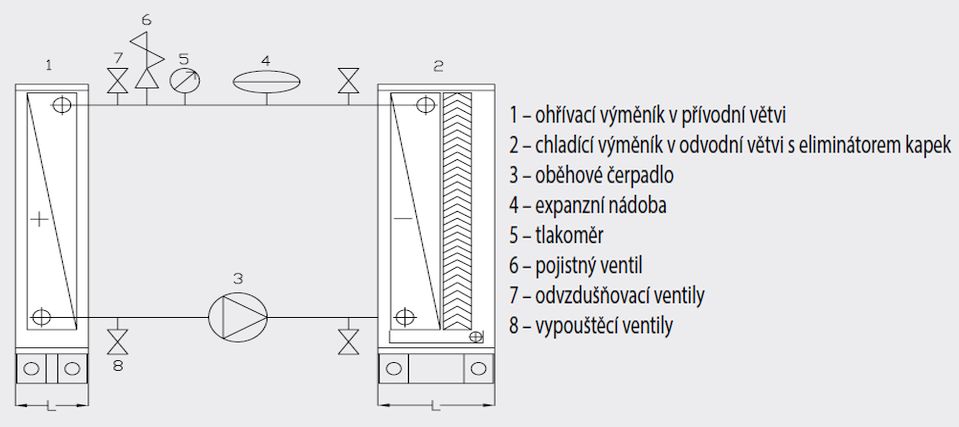
A: heating coil in the supply branch
B: cooling coil in the extract branch with droplet eliminator
C: circulation pump
D: expansion vessel
E: pressure gauge
F: safety valve
G: air vent valves
H: drain valves
¶ COMMISSIONING
¶ TASKS BEFORE COMMISSIONING
| __________________ | __________________ | ||
|---|---|---|---|
| Job number: | User: | ||
| Date: | Commissioning technician: | ||
| Project name: | |||
| Serial number: | |||
| Address: | |||
| Date of first start-up: | Position: |
Tasks for liquid circuit chambers - heat recovery
| No. | Description of service task | Task performed | Measured or set value | Note | |
|---|---|---|---|---|---|
| YES | NO | ||||
| 1.01 | Perform the same tasks as for the water heater. | ||||
| 1.02 | Perform the same tasks as for the water cooler. | ||||
| 1.03 | Check the installation and tightness of the hydraulic circuit (not included in the delivery). | ||||
| 1.04 | |||||
| 1.05 |
Tasks for liquid circuit chambers - measurement and regulation system
| No. | Description of service task | Task performed | Measured or set value | Note | |
|---|---|---|---|---|---|
| YES | NO | ||||
| 1.14 | Check the electrical connection of the liquid circuit according to the enclosed documentation (the hydraulic part is not included in the delivery). If the MANDÍK measurement and regulation system is included in the delivery, it is equipped with an output signal for operation of the circuit circulation pump. | ||||
| 1.15 | Check the electrical connection of the liquid circuit according to the enclosed documentation (the steam humidifier is not included in the delivery). If the MANDÍK measurement and regulation system is included in the delivery, it is equipped with signals for humidifier operation. | ||||
| 1.16 | |||||
| 1.17 | |||||
| 1.18 | |||||
| 1.19 |
Special tasks:
| No. | Description of service task | Task performed | Measured or set value | Note | |
|---|---|---|---|---|---|
| YES | NO | ||||
| 1.20 | |||||
| 1.21 | |||||
| 1.22 |
| In....................on.................... | |||
| ______________________ | ______________________ | ||
| Stamp and signature of the service technician: | Stamp and signature of the authorised representative of the equipment operator | ||
| ______________________ | ______________________ | ||
| Surname and number of the service technician in block capitals | Surname of the authorised representative of the operator in block capitals. |
Record the value only if it is necessary to measure a quantity.
¶ TASKS DURING COMMISSIONING
¶ TASKS DURING FIRST START-UP
During the first start-up, the following in particular is checked:
Water coils (heater/cooler):
• Tightness of the hydraulic system connection to the coil
• Correct function of the condensate drain siphon (height, filled with water)
¶ OPERATION AND MAINTENANCE
Detailed operating instructions and maintenance and service procedures are provided in the following sections and further in the individual parts of the unit.
The surface temperature of the heater and the medium connections may exceed the safe contact temperature of 60 °C during operation. Before starting any intervention or work on the chamber, wait until the coil and connections have cooled down sufficiently.
When filling, draining and venting the coil, contact between unprotected skin and the heat transfer medium must be prevented. If additives or complete ready-made mixtures for cooling systems are used, the information provided by their manufacturer for use and handling of these substances must be followed.
For further instructions for the coils, see the separate chapters "WATER HEATER CHAMBER" and "WATER COOLER CHAMBER".
¶ SERVICE AND MAINTENANCE TASK INTERVALS
| SERVICE AND MAINTENANCE TASKS | ||||||||
|---|---|---|---|---|---|---|---|---|
| Inspection task | Unit in operation Y/N* | Service/remedial action | Intervals (months) | |||||
| LIQUID CIRCUIT - HEAT RECOVERY | 1 | 3 | 6 | 12 | ||||
| 01. | Same instructions as for the water heater. | N | ||||||
| 02. | Same instructions as for the water cooler. | N | ||||||
| 03. | Check the condition and function of the hydraulic circuit. | N | repair/replacement | ✓ |
* operating status of the unit when performing the inspection