¶ GHM/PECÍN GAS/OIL HEATER CHAMBER
¶ IDENTIFICATION, ASSEMBLY AND INSTALLATION
The chamber contains an air heater with a flue gas-to-air heat exchanger. A pressure gas/oil burner of the corresponding input is then fitted to the heater. Removable panels on the service side provide access for cleaning and inspection of the heat exchanger and for fitting the actuator of the optional by-pass damper. As standard, the heating chamber is factory-fitted with a flue gas-to-air heat exchanger.
The heating chamber may also be equipped with a by-pass, or by-pass damper, for bypassing an excess air volume (as part of the unit design where the required supply air capacity is higher than the optimum air capacity through the gas heat exchanger). The by-pass section may be located in the following positions:
• above the gas/oil heat exchanger in a common chamber (vertical position)
• above the gas/oil heat exchanger in a separate chamber (vertical position)
• next to the gas/oil heat exchanger in a common chamber (horizontal position)
• both above and next to the gas/oil heat exchanger (where there is excessive remaining space around the heat exchanger)
During installation, care must be taken to ensure the correct orientation of the chamber in the assembly (cold air first cools the tube bundle carrying the flue gases and only then the combustion chamber itself). The heat exchanger is designed as a counterflow exchanger in order to use the maximum possible amount of thermal energy contained in the flue gases, including the heat component produced by possible condensation of the water vapour contained in them. The formation of condensate for higher boiler efficiency is therefore desirable and common under certain operating conditions.
An emergency thermostat is also supplied with the heating chamber to provide thermal protection of the heater.
Burners, including the gas/oil train fittings, are supplied separately in their original packaging and are always mounted on the chamber only at the final installation site of the unit.
The delivery may also include flue gas exhaust components and the by-pass damper actuator (provided that they are included and specified in the relevant technical quotation).
For GHM gas/oil heater chambers, all service and connection elements (burner mounting flange, flue gas exhaust spigot, service opening for inspection and cleaning of the heat exchanger tube bundle, condensate drain outlet) are normally located on one (service) side of the heating chamber.
The front service side of the GHM heating chamber is shown in the following figure.
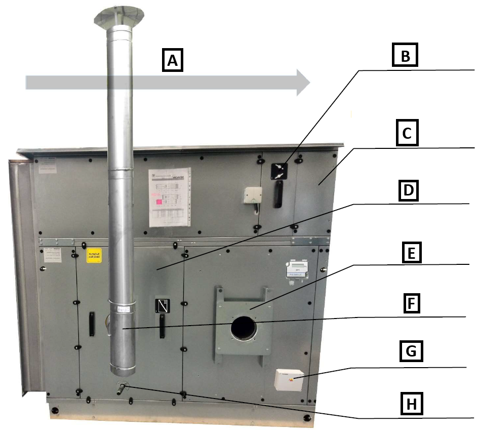
A: Airflow direction
B: Heater by-pass damper
C: Heater by-pass section (vertical design)
D: Service access to the heat exchanger
E: Connection of the heat exchanger gas/oil burner
F: Connection of the heat exchanger flue gas exhaust
G: Emergency thermostat terminal box
H: Connection of the heat exchanger condensate drain
The service panels of the by-pass damper and the heat exchanger can be removed using a 5.0 mm Allen key.
Correct function of the gas/oil heater can only be guaranteed if the following operating conditions are observed:
• nominal heat input [kW] observed
• nominal airflow rate [m3/h] observed
• correct chamber orientation during assembly – counterflow connection
• corresponding gas pressure and flow rate (see documentation)
• correct inlet air temperature (usually up to 40°C for the standard design)
• correct bypass of the heat exchanger chamber ensured (if a by-pass is provided)
• prevention of chimney effect and reverse flow
• correct connection of the emergency thermostat
Before installation, check that the local fuel distribution conditions, fuel properties, overpressure and the current heater setting are compatible.
¶ Assembly procedure at the final installation site:
The location must allow cleaning of the tube space and, if necessary, replacement of the combustion chamber. For standard maintenance, at least 600 mm is required from the burner on the service side.
The actual distance between the heat exchanger section and combustible material must not be less than the safety distance of 200 mm.
¶ Burner installation:
On the service side, a corresponding burner mounting flange is prepared and fitted at the factory. The burner body is fastened to this flange with screws. The gas train fittings may only be installed after the burner has been mounted on the chamber.
Detailed installation, adjustment and commissioning of the burner are described in the manufacturer's technical documentation enclosed in the burner package.
Detailed installation, adjustment and commissioning of the gas/oil train fittings are described in the manufacturer's technical documentation enclosed in the burner package.
The recommended basic (illustrative only) burner installation procedure is shown in the following figures. Since the heater may be equipped with different types of burners from several manufacturers, the individual illustrated parts or assemblies may differ in appearance and fixing methods for different products. Therefore, before starting installation, it is always essential to become familiar with the scope of delivery and the instructions of the manufacturer of the specific burner supplied, which are enclosed in the burner package itself:
- Mounting the burner flange to the heater flange.
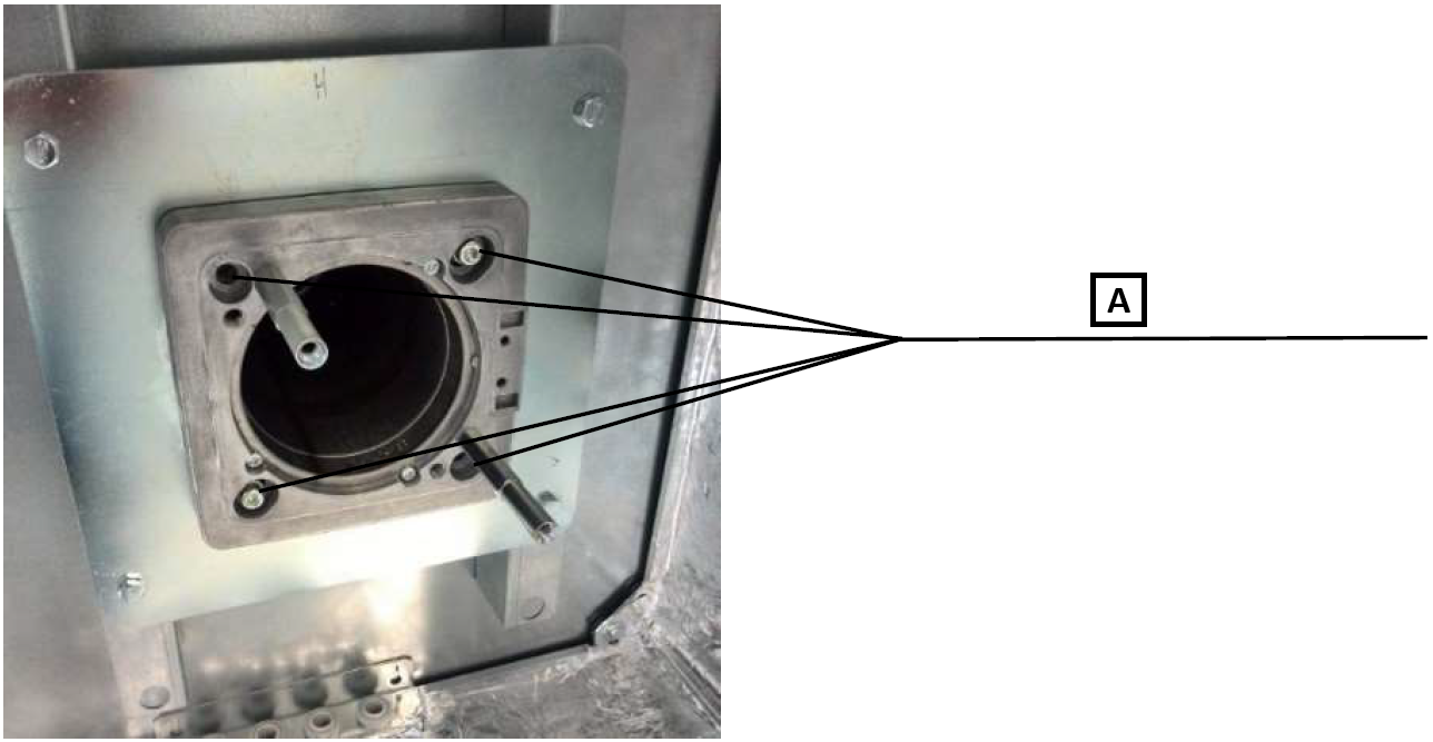
A: Fastening the flange using 4 screws included in the burner package
- Mounting the burner to the burner flange.
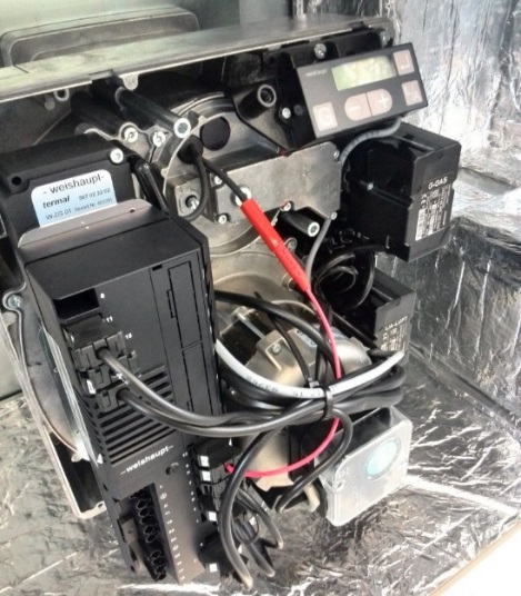
The burner mounting flange is sized for the weight of the burner itself. Care must be taken to ensure that the connected parts of the gas/oil piping do not additionally load either the burner or the heater chamber with their own weight!
When installing the fuel connection, burner and gas heater fittings, follow the instructions in the burner manual and installation and operating instructions supplied with each delivered burner in its package.
Installation may only be carried out by a qualified technician authorised to work on gas equipment and exclusively in accordance with the manufacturer's instructions. Gas equipment is subject to initial and subsequent regular inspections according to the applicable regulations. The gas connection inspection must be carried out in advance, as part of the preparation for putting the equipment into service, and should follow the physical connection of the burner to the gas piping. The inspection may only be carried out by a technician with the required professional qualification and authorisation; this inspection is not part of commissioning or adjustment and must always precede them!
The subsequent commissioning and initial adjustment of the burner must be carried out by an authorised service technician of the burner manufacturer.
¶ Installation of the burner cover (for outdoor installation):
For units intended for outdoor installation, the delivery may include a burner cover. The burner cover consists of a standard sandwich chamber and the necessary equipment (door, combustion air intake grille, openings for fittings, cable glands for power and control cables, roof and base frame).
This cover (chamber) is mounted on the heater chamber using the prepared mounting elements that are part of the fastener delivery (standard quick-release clamps used for chamber assembly).
Before connecting the cover (chamber) to the heater chamber, the cover flange must be fitted with sealing around its perimeter or the joint must be sealed with sealant to prevent water ingress.
The burner cover may be equipped with a heating element for tempering the burner space.
The convector is supplied with a socket.
¶ Installation of the flue gas exhaust (for outdoor installation):
The flue gas path must be designed in accordance with the applicable regulations and must be equipped with inspection openings. The technical specification of the gas heater always specifies the required flue gas exhaust diameter (depending on the boiler type and its heating output), and the unit diagram shows the position of the flue gas outlet spigot from the chamber. The pressure loss of the flue gas duct should not exceed 100 Pa. Drainage of condensate from the flue gas duct must also be ensured.
The supplied chimney parts are fitted with socket joints with an external clamp and seal. The supplied parts are connected to each other by their joints and the overall height is designed for the specific type of unit.
The installation of the flue duct must comply with all applicable national standards and must be carried out by a specialist company.
The flue gas duct outlet must be at least 500 mm above the chamber roof and must not be installed in such a way that flue gases can be drawn back into the unit! The condensate drain must be connected to a suitable collection tank or, after appropriate treatment, to the sewer system!
The recommended design of the complete flue gas duct is shown in the following figures.
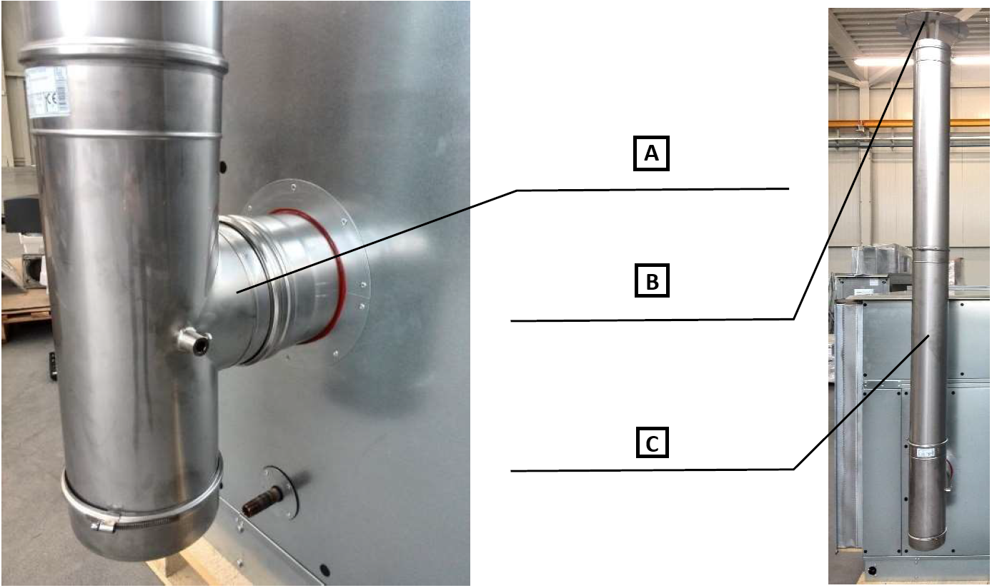
A: 90° flue branch with lower condensate drain and pocket for the Ni1000 flue gas temperature sensor. Located at the heat exchanger flue gas exhaust outlet.
B: Rain cap. It must always be the terminating element of the flue gas duct.
C: Straight sections. Supplied according to the specific type of heater and unit.
Depending on the total weight and height of the flue gas duct, it must be secured at suitable points with a static coupling to the chamber or supporting structure so that it does not excessively load the flue gas exhaust spigot.
¶ Condensate drain from the gas heat exchanger:
The heat exchanger is equipped with a condensate drain, the G½“ spigot of which is routed out through the chamber casing. The condensate drain from this spigot must be provided in a suitable way at the chamber installation site, preferably into a combined inlet shared with the condensate drain from the flue gas path. It must be ensured that the combined inlet is always lower than the condensate drain spigot from the heat exchanger and that the condensate piping has a sufficient slope away from the gas heater; only in this way will reliable condensate drainage from the heat exchanger be ensured!
¶ Emergency thermostat:
Delivery without the MANDÍK measurement and regulation system:
• Gas heating chambers are supplied without electrical control. A plastic box with an emergency thermostat is supplied with the chamber and is installed at the air outlet from the heat exchanger chamber. The thermostat is already factory-fitted.
• The emergency break thermostat is non-resetting automatically and its reactivation requires a manual reset.
• The emergency thermostat contact must be connected in the burner's supply phase to ensure that the burner is switched off in any burner state, including a fault state.
• The emergency thermostat is supplied in a plastic enclosure marked RTH.
• The heater is equipped with a terminal for protective bonding according to ČSN 32 2000-4.41.
• For the emergency thermostat, it is absolutely necessary to connect the “earth” terminal to the PE conductor to prevent any induced voltages from affecting the thermostat sensor.
Delivery with the MANDÍK measurement and regulation system:
• The above-described safety equipment is supplemented by the function of an operating, break-type resettable thermostat, provided by the controller using the flue gas sensor.
• The control system ensures fan start-up and fan run-on (cooling of the combustion chamber) after the burner is switched off.
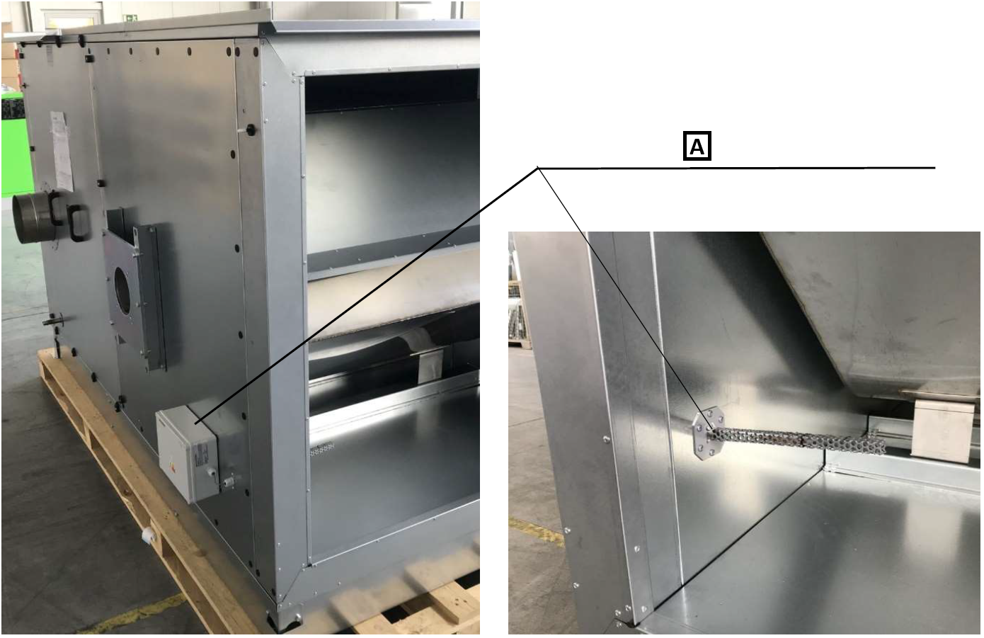
A: Location of the RTH emergency thermostat.
Description of thermostat operation:
• During operation, particular attention must be paid to tripping of the emergency thermostat. If the maximum temperature set on the emergency thermostat to 90°C, located downstream of the heat exchanger in the airflow direction, is exceeded, the burner is switched off and blocked. In order to allow a new automatic burner start, the trip on the emergency thermostat must be reset. Between the moment the burner is blocked and the emergency thermostat is unblocked, the temperature must fall below the value set on the emergency thermostat. The cause of overheating must be eliminated before the heater can be restarted.
• In the event of a mains voltage failure (while the burner is running), the temperature will rise due to the accumulated heat in the heat exchanger chamber and the fan not operating. If the temperature exceeds the value set on the emergency thermostat, the thermostat opens and disconnects the burner power supply. In the event of a short-term failure, it is necessary to wait until the chamber is cooled by the fan and only then perform a manual reset.
• After professional commissioning, the set parameters of the equipment may not be changed further in the interest of ensuring trouble-free operation.
• Control of the air capacity through the heat exchanger
If the heating chamber is equipped with a by-pass section, the optimum air capacity through the heat exchanger must be controlled. The nominal values of air capacity and pressure loss of the heat exchanger are stated in the technical specification of the unit.
The heater chamber is normally equipped with pressure taps and a controller for constant airflow control through the heat exchanger; see the figure below. A differential pressure sensor with a digital 0-10V output and a range of 0..500 Pa is used as the controller.
The by-pass damper actuator must have continuous control to ensure smooth operation from the pressure sensor on the heater. The sensor maintains the prescribed constant airflow according to the pressure loss across the boiler and passes any excess air through the by-pass. If the actuator is not installed or not included in the delivery, it must be ensured that the control system operates the by-pass damper in the manner described above.
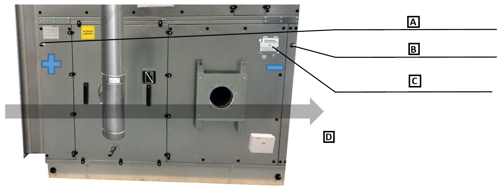
A: Pressure probe upstream of the heat exchanger
B: Pressure probe downstream of the heat exchanger
C: Constant pressure controller
D: Airflow direction
¶ Electrical installation:
Electrical installation must be carried out by a specialist company and an electrical inspection must be ensured in accordance with the applicable legal and technical regulations of the country in which the heat exchanger is put into service.
The electrical wiring of the heater burner, emergency thermostat, burner cover heating element and socket is shown in Appendix E. ELECTRICAL WIRING OF THE PECÍN GAS HEATER or in the enclosed documentation “Measurement and Regulation of KJ MANDÍK”, if the measurement and regulation system is included in the delivery.
The burner documentation is enclosed in the burner package.
The by-pass damper actuator, if included in the delivery, may be factory-fitted on request. Otherwise, the recommended installation is described in section 5.28 ACTUATOR INSTALLATION. The electrical wiring of the actuators is described in the document “Installation and Operation Manual for the Measurement and Regulation System”.
Operation of the gas/oil heater:
The gas/oil heater must not be located in an explosive atmosphere.
CAUTION: The burner must not be switched on unless simultaneous fan operation is ensured!
Airflow through the gas heater must be ensured unconditionally, i.e. the fan must be switched on first and, according to its run-up time, it is necessary to wait until the normal operating point is reached. Only after this state has been reached may the burner be switched on. Similarly, fan run-on after burner switch-off for at least 5 minutes must be ensured in order to provide sufficient cooling of the heat exchanger.
During operation, the surface temperature of the gas heater heat exchanger greatly exceeds the safe touch temperature of 60°C. Before starting any interventions or work on the chamber, wait until the heat exchanger has cooled sufficiently!
For outdoor installation of the heater, suitable heating, such as a heating cable, is recommended for correct condensate drain function during the winter period.
¶ COMMISSIONING
¶ TASKS BEFORE COMMISSIONING
| __________________ | __________________ | ||
|---|---|---|---|
| Job number: | User: | ||
| Date: | Commissioning technician: | ||
| Project name: | |||
| Serial number: | |||
| Address: | |||
| Date of first start-up: | Position: |
Tasks for gas heater chambers - GHM/PECÍN
| No. | Description of service task | Task performed | Measured or set value | Note | |
|---|---|---|---|---|---|
| YES | NO | ||||
| 1.01 | Check cleanliness and absence of damage on the gas heater and tighten the heat exchanger service cover. | ||||
| 1.02 | Check free rotation of the by-pass damper. | ||||
| 1.03 | Check stress on the spigots of all connections - no components may load the connection spigots. | ||||
| 1.04 | Check execution and completeness of the flue gas path; check execution of condensate drains. | ||||
| 1.05 | Check fastening of the burner to the heater flange. | ||||
| 1.06 | Check the burner nameplate; the burner output must correspond to the heater output range. | ||||
| 1.07 | Check the burner and gas connection according to the list of necessary checks in the burner manual. |
Tasks for gas heater chambers - GHM/PECÍN - MaR
| No. | Description of service task | Task performed | Measured or set value | Note | |
|---|---|---|---|---|---|
| YES | NO | ||||
| 1.15 | Check the power supply switch and the prescribed protection. | ||||
| 1.16 | Check correct electrical wiring of the burner electrical connection according to the enclosed burner documentation and nameplate values. | ||||
| 1.17 | Check connection and verify the function of the emergency thermostat for thermal protection of the PECÍN heater. | ||||
| 1.20 | Check wiring according to the electromagnetic compatibility requirement, if required. | ||||
| 1.21 | |||||
| 1.22 |
Special tasks:
| No. | Description of service task | Task performed | Measured or set value | Note | |
|---|---|---|---|---|---|
| YES | NO | ||||
| 1.24 | |||||
| 1.25 | |||||
| 1.26 | |||||
| 1.27 |
| In....................on.................... | |||
| ______________________ | ______________________ | ||
| Stamp and signature of service technician: | Stamp and signature of the authorised representative of the equipment operator | ||
| ______________________ | ______________________ | ||
| Surname and number of service technician in block letters | Surname of the authorised representative of the operator in block letters. |
*Enter the value only if a quantity must be measured.
¶ TASKS DURING COMMISSIONING
¶ TASKS DURING FIRST START-UP
During first start-up, the following in particular is checked:
Pecín gas heater:
• Correct burner adjustment and operation (combustion air quantity, supplied gas quantity, tightness of the burner connection to the heat exchanger, tightness of the gas train fittings and gas connection, ...) - always carried out by a specialist service technician of the burner manufacturer
• Optimum flue gas temperature — should not exceed 200°C
• Air downstream of the heat exchanger does not exceed +45°C
• Correct direction of rotation of the by-pass damper, or switching of the actuator switch, see section 5.28 ACTUATOR INSTALLATION
¶ OPERATION AND MAINTENANCE
Detailed operation instructions and maintenance and service procedures are given in the following sections and further for the individual parts of the unit.
| SERVICE AND MAINTENANCE TASKS | ||||||||
|---|---|---|---|---|---|---|---|---|
| Inspection task | Unit in operation Y/N* | Service/remedy method | Intervals (months) | |||||
| PECÍN GAS HEATER | 1 | 3 | 6 | 12 | ||||
| 01. | Check condition of the heat exchanger (damage, corrosion). | N | repair/replacement | ✓ | ||||
| 02. | Check external contamination of the heat exchanger. | N | cleaning | ✓ | ||||
| 03. | Check internal contamination of the heat exchanger - flue gas path. | N | cleaning | ✓ | ||||
| 04. | Check gas connection. | N | repair/replacement | ✓ | ||||
| 05. | Check condition and correct function of the burner - always carried out by a service technician of the burner manufacturer. | N | repair/replacement | ✓ | ||||
| 06. | Check function of burner cover heating for outdoor installation. | N | repair/replacement | ✓ | ||||
| 07. | Check function of the emergency thermostat. | N | repair/replacement | ✓ | ||||
| 08. | Check condition and patency of the heater flue gas exhaust. | N | repair/replacement | ✓ | ||||
| 09. | Check function of the condensate drain from the flue gas exhaust. | N | repair/replacement | ✓ | ||||
| 10. | Check free rotation of the by-pass damper. | N | repair/replacement | ✓ | ||||
| 11. | Check contamination of the by-pass damper. | N | reactivation | ✓ |
* operating state of the unit during inspection
¶ SERVICE AND MAINTENANCE TASK INTERVALS
¶ GAS HEATING CHAMBER
During operation, the surface temperature of the heater and flue gas duct greatly exceeds the safe touch temperature of 60°C. Before starting any interventions or work on the chamber, wait until the heat exchanger, flue gas duct and chamber have cooled sufficiently!
The blades of the open damper must be secured against spontaneous or accidental closing. Never put limbs between the blades of an open damper; there is a risk of serious injury!
Check the condition and contamination of the heat exchanger; clean with a vacuum cleaner if necessary.
Check the contamination, any damage and mobility of the damper blades. Remove any dust deposits with a vacuum cleaner; the surface of the damper blades can then also be cleaned with a damp cloth. The plastic gear wheels of the dampers are made of a material that does not require additional lubrication.
For dampers with linkage, lubricate the necessary points of the lever transmission with lubricating spray.
Check the condition and function of the condensate drains from the heat exchanger and from the flue gas duct, and check the patency of the drain and any following siphon; clean as required and top up with water. For the gas connection and flue gas duct, check their tightness and function even outside the precisely prescribed inspection intervals.
¶ PECÍN GAS BOILER
For warranty claims, service tasks on the burner may only be carried out by a service technician of the burner manufacturer or by an authorised service technician of the burner manufacturer.
For warranty claims, service tasks on the heat exchanger (cleaning the tube bundle, etc.) may only be carried out by a service technician of MANDÍK, a.s. or by an authorised service technician of MANDÍK, a.s.
For warranty claims, service tasks on the chimney flue gas exhaust system may only be carried out by a specialist company.
Maintenance of the burner and gas train fittings is governed by the instructions in the manufacturer's manual and technical documentation enclosed in the burner package; these should subsequently be stored at the operating site of the combustion equipment.
During maintenance of the heat exchanger section, always check the tightening of the burner flange and burner at least once before the start of the heating season. After removing the tube bundle cover, turn the flue gas turbulators to loosen deposits; remove the turbulators as required and sweep the tubes. After checking and, if necessary, replacing the cover seal, return the cover to the heat exchanger and tighten the screws.