¶ MONZUN GAS HEATER SECTION
¶ IDENTIFICATION, ASSEMBLY AND INSTALLATION
The section contains a gas heater with or without a thermal by-pass.
The heating section is factory-fitted as standard with a flue-gas-to-air heat exchanger and, where applicable, with a by-pass damper.
The heating section is equipped with an automatic system for controlling heater operation.
The section is always supplied including a premix burner and including gas train fittings.
On the service side, doors or removable panels provide access to the burner, ignition automation, and also for cleaning and inspection of the heat exchanger and for fitting the by-pass damper actuator.
The delivery may also include flue gas exhaust components and the by-pass damper actuator (provided that they are included and specified in the relevant technical offer).
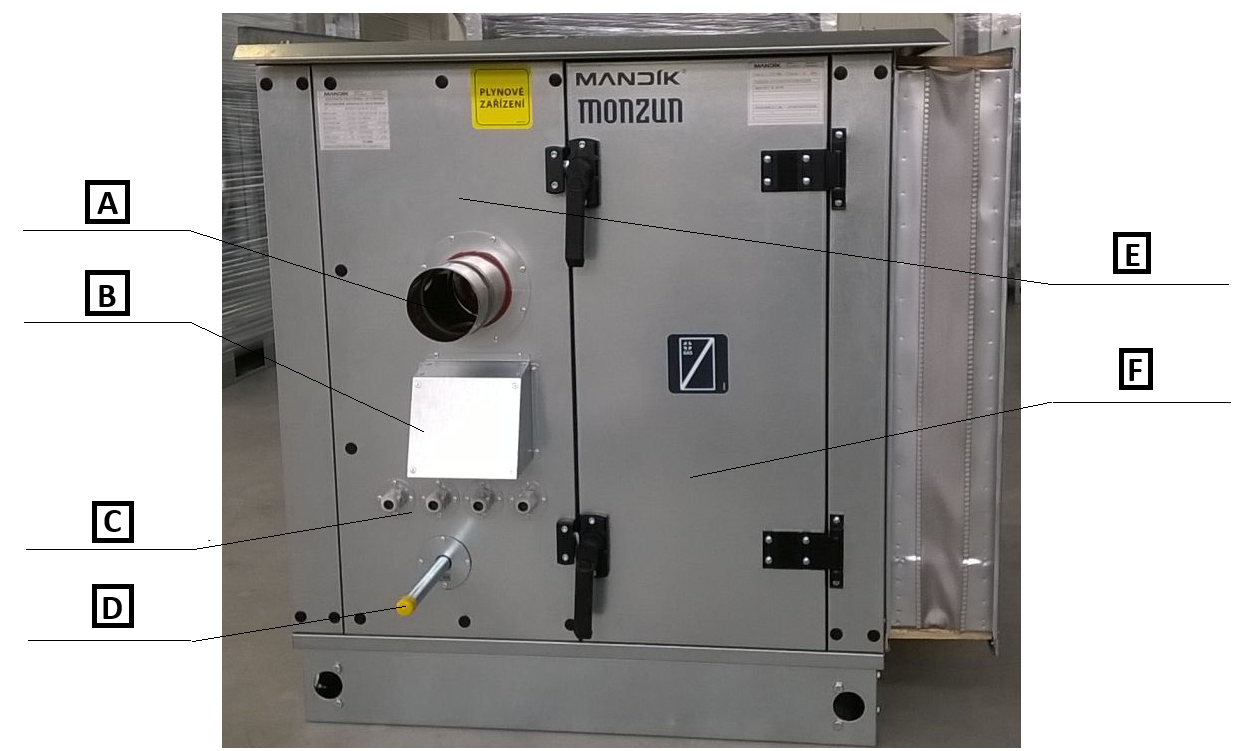
A: flue gas exhaust
B: burner intake cover
C: cable glands
D: gas connection
E: fixed panel
F: service door
Assembly procedure at the final installation site:
¶ Installation of the gas connection:
The gas connection is factory-prepared and fitted on the service side.
The gas connection on the section is not designed to carry the weight of the connected gas piping. Care must be taken to ensure that the connected parts of the gas piping do not load either the connection or the gas heater section with their own weight!
When installing the gas connection, follow the instructions contained in the manual and in the installation and operating instructions for the MONZUN gas heater, which are included in the documentation for each heater supplied. The gas piping must be terminated with a gas ball valve installed upstream of the heater inlet. We recommend that the connection between this valve and the heater connection is made using a flexible gas hose.
Installation may be carried out only by a qualified technician authorised to work on gas equipment and exclusively in accordance with the manufacturer’s instructions. Gas equipment is subject, under the applicable regulations, both to initial inspection and to subsequent regular inspections. The gas connection inspection must be carried out in advance as part of the preparation for commissioning the equipment and should follow the physical connection of the heater to the gas piping. The inspection may only be carried out by a technician with professional qualification and the relevant authorisation. This inspection is not part of commissioning or adjustment and must always precede them!
Commissioning of the burner and its initial adjustment must always be carried out by a service technician of MANDÍK, a.s. or by an authorised service technician of MANDÍK, a.s.
¶ Installation of the flue gas exhaust:
The flue gas path must be designed in accordance with the applicable regulations. The technical specification of the gas heater always states the required flue gas exhaust diameter (depending on the boiler type and its heating output), and the unit diagram shows the position of the flue gas outlet spigot from the section. The premix burner fan also provides forced flue gas exhaust. This fan is capable of overcoming a flue duct pressure loss of max. 100 Pa. If the combustion air for the burner is supplied through a coaxial chimney, the sum of the pressure losses at the combustion air intake and in the chimney must not exceed 100 Pa. Condensate drainage from the flue duct must also be ensured. During normal operation, only a small amount of condensate is produced and only for a short time after the heater is switched on; after the chimney has warmed up, it is practically no longer present. However, care must be taken to ensure that the condensate drain inlet is always lower than the lower edge of the flue gas exhaust spigot from the heat exchanger, thus preventing possible flooding of the heat exchanger. Any condensate piping must have a sufficient fall away from the chimney to ensure reliable condensate drainage!
The electrical connection of the heater is specified in Annex F. ELECTRICAL CONNECTION OF THE MONZUN GAS HEATER or in the enclosed documentation “Measurement and Regulation of MANDÍK KJ”, if the MaR system is included in the delivery.
The by-pass damper actuator, if included in the delivery, may be factory-fitted upon request. Otherwise, the recommended installation is specified in section 5.28 INSTALLATION OF ACTUATORS. The electrical connection of the actuators is specified in the document “Installation and Operation Manual for the MaR System”.
For the by-pass damper actuator, the stops defining the end positions of the damper must be adjusted so that the minimum prescribed air flow through the by-pass is maintained. This minimum flow rate is always stated in the technical specification of the delivered unit. This means that, in the closed position, the end position of the damper actuator must still ensure partial opening and thus the prescribed air flow through the by-pass. If the actuator is not installed or manual control is fitted, this minimum partial opening of the damper must again be ensured by a suitable method.
The internal installation and access to the by-pass actuator are shown in the following figure.
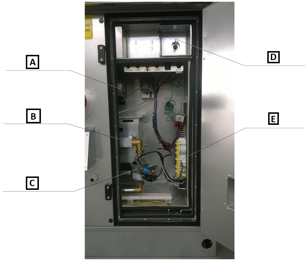
A: flue gas exhaust fan
B: burner
C: burner fittings
D: damper shaft
E: terminal block
¶ Operation of the gas heater:
CAUTION: The burner must not be switched on unless simultaneous fan operation is ensured!
Air flow through the gas heater must be ensured without exception, i.e. the fan must first be switched on and, according to its start-up time, it is necessary to wait until the normal operating point is reached. Only after this state has been reached may the burner be switched on. Likewise, fan run-on for at least 5 minutes after the burner is switched off must be ensured to provide sufficient cooling of the heat exchanger.
During operation, the surface temperature of the gas heater heat exchanger significantly exceeds the safe contact temperature of 60°C. Before starting any intervention or work on the section, wait until the heat exchanger has cooled down sufficiently!
¶ COMMISSIONING
¶ TASKS BEFORE COMMISSIONING
| __________________ | __________________ | ||
|---|---|---|---|
| Contract number: | User: | ||
| Date: | Commissioning technician: | ||
| Project name: | |||
| Serial number: | |||
| Address: | |||
| Date of first start-up: | Position: |
Tasks for MONZUN gas heater sections
| No. | Service task description | Task performed | Measured or set value | Note | |
|---|---|---|---|---|---|
| YES | NO | ||||
| 1.08 | Check the cleanliness and undamaged condition of the gas heater; check the function of the service doors. | ||||
| 1.09 | Check the free rotation of the by-pass damper (if it is part of the heater). | ||||
| 1.10 | Check the load on the spigots of all connections - no components may load the connection spigots. | ||||
| 1.11 | Check the design and completeness of the flue gas path; check the condensate drain design. | ||||
| 1.12 | Check the unobstructed passage of the combustion air intake grille on the section panel. | ||||
| 1.13 | Check the MONZUN heater nameplate and the conformity of the data with the technical specification of the heater. | ||||
| 1.14 | Check the burner and gas connection according to the list of necessary checks in the heater manual. |
Tasks for MONZUN gas heater sections - MaR
| No. | Service task description | Task performed | Measured or set value | Note | |
|---|---|---|---|---|---|
| YES | NO | ||||
| 1.15 | Check the power supply switch and the prescribed protection. | ||||
| 1.16 | Check the correct electrical connection of the burner electrical supply according to the enclosed burner documentation and nameplate values. | ||||
| 1.17 | Check the correct electrical connection of the MONZUN heater electrical supply according to the enclosed documentation, TPM043/05 MONZUN KLIM and nameplate values. | ||||
| 1.18 | Check the connection and verify the function of the operating and emergency thermostat of the MONZUN heater thermal protection. | ||||
| 1.19 | Check the connection according to the electromagnetic compatibility requirement, if required. | ||||
| 1.20 | |||||
| 1.21 |
Special tasks:
| No. | Service task description | Task performed | Measured or set value | Note | |
|---|---|---|---|---|---|
| YES | NO | ||||
| 1.22 | |||||
| 1.23 | |||||
| 1.24 | |||||
| 1.25 |
| In....................on.................... | |||
| ______________________ | ______________________ | ||
| Stamp and signature of the service technician: | Stamp and signature of the authorised representative of the equipment operator | ||
| ______________________ | ______________________ | ||
| Surname and number of the service technician in block capitals | Surname of the authorised representative of the operator in block capitals. |
Enter the value only if it is necessary to measure a quantity.
¶ TASKS DURING COMMISSIONING
¶ TASKS DURING FIRST START-UP
During the first start-up, the following in particular is checked:
MONZUN gas heater:
• The heater is commissioned exclusively by a service technician of MANDÍK, a.s. or by a person authorised by MANDÍK, a.s. for service activities.
• The air downstream of the heat exchanger does not exceed +45°C
• Correct rotation direction of the by-pass damper, or switching the actuator selector switch; see section 5.28 INSTALLATION OF ACTUATORS
¶ OPERATION AND MAINTENANCE
Detailed operating instructions and maintenance and service procedures are given in the following sections and also for the individual parts of the unit.
| SERVICE AND MAINTENANCE TASKS | ||||||||
|---|---|---|---|---|---|---|---|---|
| Inspection task | Unit in operation Y/N* | Service/remedy method | Intervals (months) | |||||
| MONZUN GAS HEATER | 1 | 3 | 6 | 12 | ||||
| 01. | Check the condition of the heat exchanger (damage, corrosion). | N | repair/replacement | ✓ | ||||
| 02. | Check external contamination of the heat exchanger. | N | cleaning | ✓ | ||||
| 03. | Check internal contamination of the heat exchanger - flue gas path. | N | cleaning | ✓ | ||||
| 04. | Check the gas connection. | N | cleaning | ✓ | ||||
| 05. | Check the condition and correct function of the burner - always carried out by a service technician of the burner manufacturer. | N | cleaning | ✓ |
* operating state of the unit when the inspection is carried out
¶ INTERVALS OF SERVICE AND MAINTENANCE TASKS
For warranty claims, service tasks may be carried out only by a service technician of MANDÍK, a.s. or by an authorised service technician of MANDÍK, a.s.
When maintaining the heater, check the tightness of the bolted connections in the burner area and test the functionality of the flue gas extraction fan, thermostats and indicator lights on the service panel. Also check the electrical connection and tightening of the cable terminals. If necessary, vacuum the dust and check the free passage of the combustion air intake opening for the burner.