¶ WATER HEATER, CONDENSER AND STEAM HEATER CHAMBER
¶ IDENTIFICATION, ASSEMBLY AND INSTALLATION
The chamber with a water heater contains a finned heat exchanger intended for water or a water/glycol mixture as the heat transfer medium.
The chamber with a condenser heater contains a finned heat exchanger intended for refrigerant as the heat transfer medium.
The heating chamber is fitted with the heat exchanger as standard at the factory.
The heating chamber of the water heater is fitted as standard at the factory with a frame for the capillary frost protection thermostat.
The mixing unit for regulating the heating capacity, if included in the water heater delivery, is supplied in a cardboard box in one of the unit chambers. The recommended installation of the mixing unit is described in section 5.25 INSTALLATION OF THE MIXING UNIT. The electrical connection of the mixing unit is described in the document “Manual for Installation and Operation of the Measurement and Regulation System”.
The capillary frost protection thermostat, if included in the delivery, may be fitted at the factory on request. Otherwise, the recommended installation is described in the document “Manual for Installation and Operation of the Measurement and Regulation System”.
The heat exchanger connections are marked INLET/OUTLET to ensure correct connection of the mixing unit or the hydraulic system piping; see the following figure.
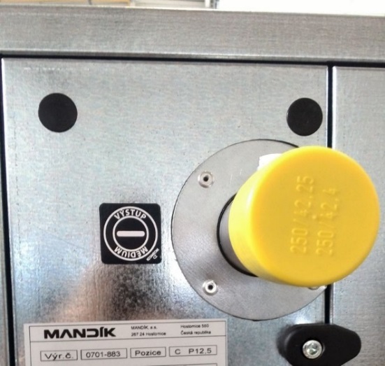
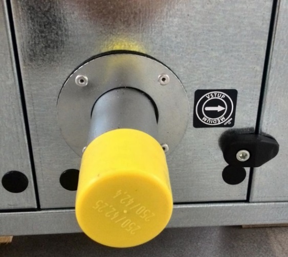
The heat exchanger outlets are provided with threads for connection to the hydraulic system.
All piping must be fixed independently of the heat exchangers. The piping systems for operating fluids must not act on the unit blocks or on the heat exchangers by their weight or expansion forces. The connections must be made so that pipe expansion due to temperature does not cause excessive loading of the connection nozzles.
The connection must be tightened using two spanners. Otherwise, there is a risk of thread deformation!
The air vent valve, if not installed, must be located at the highest point of the hot water supply.
The heat exchanger must always be connected in counter-flow! See the following figure.
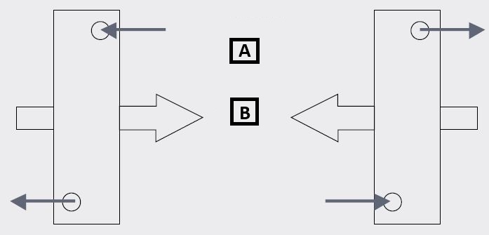
A: heating / cooling medium
B: air
Water for water heat exchangers must not contain impurities causing fouling, especially corrosion products from steel and cast-iron parts. To prevent these impurities from forming, chemically treated water with parameters according to ČSN 07 7401 must be used.
• pH value 7–9.
• Water hardness 1.0 mval.l.
• Chloride content max. 30 mg.l.
• Phosphate content calculated as P2O5, min. 15 mg.l.
¶ COMMISSIONING
¶ TASKS BEFORE COMMISSIONING
| __________________ | __________________ | ||
|---|---|---|---|
| Order number: | User: | ||
| Date: | Commissioning technician: | ||
| Project name: | |||
| Serial number: | |||
| Address: | |||
| Date of initial start-up: | Position: |
Tasks for heat exchanger chambers - water heater
| Number | Description of service task | Task performed | Measured or set value | Note | |
|---|---|---|---|---|---|
| YES | NO | ||||
| 1.01 | Check the tightness of the operating fluid piping/mixing unit connection to the heat exchanger. | ||||
| 1.02 | Check the venting of the heat exchanger. | ||||
| 1.03 | Check the cleanliness and absence of damage to the heat transfer surface of the heat exchanger. | ||||
| 1.04 | Check that the connections are made so that thermal expansion of the pipes does not cause excessive loading of the connections. | ||||
| 1.05 | Water for the water heat exchanger must not contain impurities causing fouling of the tubes. | ||||
| 1.06 | Check the load on the heat exchanger nozzles – no parts of the heating water source system (piping, mixing unit, etc.) may load the heat exchanger nozzles. | ||||
| 1.07 | Check that the heat exchanger is connected in counter-flow – according to the installation instructions. |
Tasks for heat exchanger chambers - measurement and regulation system
| Number | Description of service task | Task performed | Measured or set value | Note | |
|---|---|---|---|---|---|
| YES | NO | ||||
| 1.16 | Check the installation and connection of the mixing unit/3-way valve according to the installation instructions – for the heater and cooler, if present. | ||||
| 1.17 | Check the installation and connection of the heater capillary frost protection thermostat according to the installation instructions. | ||||
| 1.18 | Check the function of the heater capillary frost protection thermostat, e.g. using special freezing gas or by shutting off the heating water when the supply air temperature at the heat exchanger is sufficiently high. | ||||
| 1.19 | |||||
| 1.20 | |||||
| 1.21 |
Special tasks:
| Number | Description of service task | Task performed | Measured or set value | Note | |
|---|---|---|---|---|---|
| YES | NO | ||||
| 1.24 | |||||
| 1.25 | |||||
| 1.26 | |||||
| 1.27 |
| At....................on.................... | |||
| ______________________ | ______________________ | ||
| Stamp and signature of the service technician: | Stamp and signature of the authorized representative of the equipment operator | ||
| ______________________ | ______________________ | ||
| Surname and number of the service technician in block capitals | Surname of the authorized representative of the operator in block capitals. |
*Enter the value only if it is necessary to measure a quantity.
¶ TASKS DURING COMMISSIONING
¶ TASKS DURING INITIAL START-UP
During initial start-up, the following in particular is checked:
Water heat exchangers (heater/cooler):
• Tightness of the hydraulic system connection to the heat exchanger
• Correct function of the condensate drain siphon (height, filled with water)
¶ OPERATION AND MAINTENANCE
Detailed operating instructions and maintenance and service procedures are given in the following sections and further in the individual parts of the unit.
The surface temperature of the heater and media connections during operation may exceed the safe touch temperature of 60°C. Before starting any interventions or work on the chamber, wait until the heat exchanger and connections have cooled sufficiently.
When filling, draining and venting the heat exchanger, contact between unprotected skin and the heat transfer medium must be prevented. If additives or complete ready-made mixtures for heating systems are used, the manufacturer’s information on the use and handling of these substances must be observed.
For heat exchangers, we check fouling, tightness and possible damage. Fouling is removed by blowing through with air, steam or a hot-water pressure cleaner against the direction of airflow. In all cases, care must be taken to prevent deformation of the heat exchanger fins; for this reason, high-pressure equipment, whether using water or air, should not be used for cleaning.
Regularly check the tightness of the connection fittings and the functionality of the air vent valves, or the tightness of the refrigerant circuit for the condenser. Independently of the specified maintenance intervals, always before the cold period of the year, check the function of the frost protection and, if applicable, check the concentration of the antifreeze mixture. For water heat exchangers, before longer shutdowns (unless they are filled with an antifreeze mixture of sufficient concentration), drain the medium. Draining the medium alone does not guarantee that all liquid has been emptied from the heat exchanger; the heat exchanger must also be blown through with compressed air without fail! Before a longer shutdown of the condenser, it must be ensured that the refrigerant circuit is hermetically sealed and that moisture does not condense on the heat exchanger. It is recommended to dry the heat exchanger and protect it from dust.
¶ SERVICE AND MAINTENANCE TASK INTERVALS
| SERVICE AND MAINTENANCE TASKS | ||||||||
|---|---|---|---|---|---|---|---|---|
| Inspection task | Unit in operation Y/N* | Service/remedy method | Intervals (months) | |||||
| WATER HEATER | 1 | 3 | 6 | 12 | ||||
| 01. | Check that the heat transfer surface of the heat exchanger is not damaged. | N | repair/replacement | ✓ | ||||
| 02. | Check the cleanliness of the heat transfer surface of the heat exchanger. | N | cleaning | ✓ | ||||
| 03. | Check the tightness of the heat exchanger on the operating fluid side. | N | repair | ✓ | ||||
| 04. | Check the function of the heat exchanger frost protection (always before the heating season). | N | repair/measurement and regulation system | ✓ | ||||
| 05. | Check the condition of the heat exchanger hydraulic circuit connection. | N | repair | ✓ | ||||
| 06. | Check the condition and function of the mixing unit according to the manufacturer’s instructions. | N | repair | ✓ |
* unit operating status when performing the inspection
<!--
new line via html