¶ ELECTRIC HEATER CHAMBER
¶ IDENTIFICATION, ASSEMBLY AND INSTALLATION
The chamber contains a heat exchanger with resistance heating elements, an operating thermostat and a safety thermostat with fixed set values of +50°C. The heating rods are already interconnected as standard at the factory and, together with the thermostats, are routed to the terminal box. The terminal box is attached to the heat exchanger on the service side.
The heating chamber is fitted with the heat exchanger as standard at the factory.
The electric heat exchanger is designed for a voltage of 3~400V/50HZ and may contain several sections; the maximum power input of one section may be 48 kW. The electric heater diagram is shown in the figure:
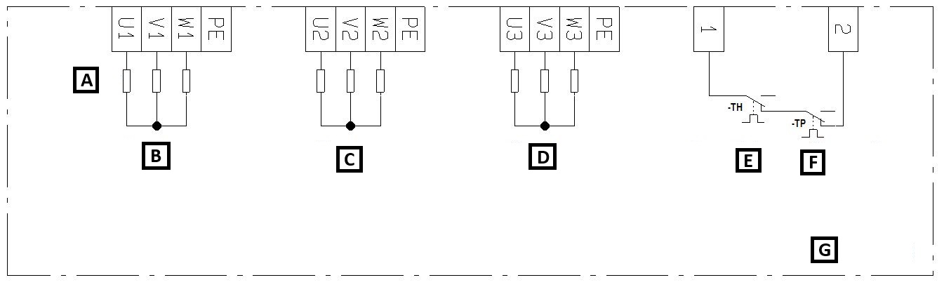
A: Heating rods
B: 1st section
C: 2nd section
D: 3rd section
E: Safety thermostat
F: Operating thermostat
G: Electric heater
Any interventions in the electric heater may only be carried out by a worker with professional qualifications according to the valid regulation of the country in which the unit is put into operation!
Access to the terminal box is possible after removing the service panel using a 5.0 mm Allen key. For connecting the power conductors, the chamber is equipped with PG screw cable glands located on the removable panel; see the following figure.
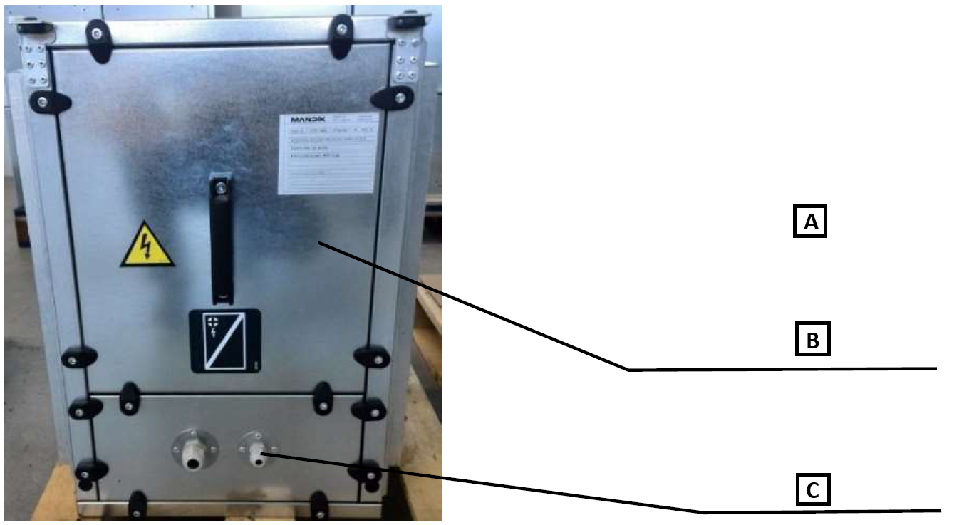
A: Access to the terminal box
B: The panel can be removed using a 5.0 mm Allen key
C: Cable glands
The electrical connection of the heater is specified in the heater documentation or in the attached “Measurement and Regulation for MANDÍK AHU” documentation, if the measurement and regulation system is included in the delivery.
The heater documentation (Initial Inspection Report, Certificate of Quality, EC Declaration of Conformity, Installation and Operating Instructions, Wiring Diagram) is enclosed inside the heater.
The operating and safety thermostats must always be properly connected to the control system. The thermostats are connected in series and their contacts are closed at safe air temperatures inside the heater. When a contact opens, the electric heater must be switched off. The operating thermostat resets automatically when the heater has cooled down; the safety thermostat must be reset manually. Between the moment the thermostat overheats and the possibility of manual release, the temperature must drop below the value set on the thermostat. The cause of overheating must be removed before the heater can be started again. The operating thermostat is set as standard to a temperature of approx. 50°C in the air flow; the safety thermostat is set to approx. 50°C in a suitable area of the heater affected by radiant heat from the heating elements.
The air velocity in the active cross-section of the unit must not be lower than 1 m/s; otherwise the heating elements will overheat. For units with variable air flow, this must be handled by setting a higher minimum speed value.
Operation of the electric heater:
ATTENTION: The heater must not be switched on unless simultaneous fan operation is ensured!
Air flow through the heater must be ensured without exception, i.e. first switch on the fan and wait, according to its start-up time, until the normal operating point is reached. Only after this state has been reached may the heater be started. Likewise, fan run-on for at least 5 minutes after the heater has been switched off must be ensured so that the heating elements are sufficiently cooled. If this condition is not observed, the manufacturer assumes no liability for damage caused by heat accumulated in the body of the electric heater.
During operation, the surface temperature of the heater heating elements greatly exceeds the safe touch temperature of 60°C. Before starting any interventions or work on the chamber, wait until the heat exchanger has cooled down sufficiently!
A standard electric heater must not be located in a potentially explosive atmosphere. Explosive and easily flammable substances must not be stored near the electric heater.
¶ COMMISSIONING
¶ TASKS BEFORE COMMISSIONING
X
¶ TASKS DURING COMMISSIONING
¶ TASKS DURING INITIAL START-UP
During initial start-up, the following in particular is checked:
Electric heater:
• The air velocity must not fall below 1 m/s.
• Measuring current consumption at all output stages on all phases
-- it must not exceed the nameplate data
¶ ELECTRIC HEATER IN THE CPV AND CPX UNIT:
Detailed operating instructions and maintenance and service procedures are provided in the following paragraphs and also for the individual parts of the unit.
The heater unit contains a heat exchanger with resistance heating elements, an operating thermostat with a fixed set value of +50°C and a safety thermostat set to +80°C. The heating rods are already interconnected as standard at the factory and, together with the thermostats, are routed to the terminal box. The terminal box is attached to the heat exchanger for CPV on the service side and for CPX on the door side.
For the electric heater, the minimum face velocity of 1 m/s, which ensures heat removal from the heating elements, must always be maintained under all operating conditions and modes.
The electric heat exchanger is designed for a voltage of 3~400V/50HZ and may contain several sections.
During operation, the surface temperature of the heating rods greatly exceeds the safe touch temperature of 60°C. Before starting any interventions or work on the chamber, wait until the heating rods and chamber have cooled down sufficiently!
Any interventions in the electric heater may only be carried out by a worker with professional qualifications according to the valid regulation of the country in which the unit is put into operation.
Check the condition and contamination of the heating elements and clean them with a vacuum cleaner if necessary.
The functionality of the airflow monitoring device and of the operating and safety thermostats must also be checked. For the electric heating chamber, the minimum face velocity of 1 m/s, which ensures heat removal from the heating elements, must always be maintained under all operating conditions and modes.
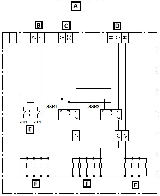
| A: Electric heating | B: Control power supply |
| C: PWM signal | D: Power supply |
| E: Protective thermostats | F: Heating rods |
Access to the terminal box is possible after removing the cover using a 5.0 mm Allen key.
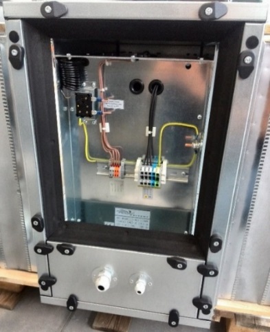
The heater terminal box is equipped with a DIN rail with terminals for power supply connection, an SSR relay for power switching, and an operating and safety thermostat for safe operation; see the figure:
| A: DIN RAIL WITH TERMINALS | B: SAFETY THERMOSTAT |
| C: OPERATING THERMOSTAT | D: SSR RELAY |
The operating and safety thermostats must always be properly connected to the control system. The thermostats are connected in series and their contacts are closed at safe air temperatures inside the heater. When a contact opens, the electric heater must be switched off. The operating thermostat resets automatically when the heater has cooled down; the safety thermostat must be reset manually. Between the moment the thermostat overheats and the possibility of manual release, the temperature must drop below the value set on the thermostat. The cause of overheating must be removed before the heater can be started again. The operating thermostat is set as standard to a temperature of approx. 50°C in the air flow; the safety thermostat is set to approx. 80°C in a suitable area of the heater affected by radiant heat from the heating elements.
| A: POSITION OF THE SAFETY THERMOSTAT IN THE REST STATE. IN CASE OF A FAULT, THE RED RESET MUST BE MANUALLY PRESSED BACK IN |
| B: SETTING THE CUT-OUT TEMPERATURE OF THE OPERATING THERMOSTAT |
| C: SETTING THE CUT-OUT TEMPERATURE OF THE SAFETY THERMOSTAT |
The electrical connection of the heater is specified in the attached “MANDÍK Measurement and Regulation” documentation.
The air velocity in the active cross-section of the unit must not be lower than 1 m/s; otherwise the heating elements will overheat. For units with variable air flow, this must be handled by setting a higher minimum speed value.
Operation of the electric heater: ATTENTION: The heater must not be switched on unless simultaneous fan operation is ensured!
Air flow through the heater must be ensured without exception, i.e. first switch on the fan and wait, according to its start-up time, until the normal operating point is reached. Only after this state has been reached may the heater be started. Likewise, fan run-on for at least 5 minutes after the heater has been switched off must be ensured so that the heating elements are sufficiently cooled. If this condition is not observed, the manufacturer assumes no liability for damage caused by heat accumulated in the body of the electric heater.
A standard electric heater must not be located in a potentially explosive atmosphere. Explosive and easily flammable substances must not be stored near the electric heater.
¶ SERVICE AND MAINTENANCE TASK INTERVALS
During operation, the surface temperature of the heating rods greatly exceeds the safe touch temperature of 60°C. Before starting any interventions or work on the chamber, wait until the heating rods and chamber have cooled down sufficiently!
Any interventions in the electric heater may only be carried out by a worker with professional qualifications according to the valid regulation of the country in which the unit is put into operation.
Check the condition and contamination of the heating elements and clean them with a vacuum cleaner if necessary.
The functionality of the airflow monitoring device and of the operating and safety thermostats must also be checked. For the electric heating chamber, the minimum face velocity of 1 m/s, which ensures heat removal from the heating elements, must always be maintained under all operating conditions and modes.
| SERVICE AND MAINTENANCE TASKS | ||||||||
|---|---|---|---|---|---|---|---|---|
| Check task | Unit in operation Y/N* | Service/remedy method | Intervals (months) | |||||
| ELECTRIC HEATER | 1 | 3 | 6 | 12 | ||||
| 01. | Check that the heating elements are not damaged. | N | replacement | ✓ | ||||
| 02. | Check the cleanliness of the terminal box. | N | cleaning | ✓ | ||||
| 03. | Check the cleanliness of the heating elements. | N | cleaning | ✓ | ||||
| 04. | Check the condition of the electrical connection of the heating elements and protections (condition of cables, tightening of cables, …). | N | repair | ✓ | ||||
| 05. | Check the function of the operating and safety thermostat. | N | value from measurement and regulation system | ✓ |
* unit operating status when the check is performed