¶ ROTARY REGENERATIVE HEAT EXCHANGER CHAMBER
¶ IDENTIFICATION, ASSEMBLY AND INSTALLATION
The chamber contains an air-to-air rotary regenerative heat exchanger.
The chamber is fitted with a rotary regenerative heat exchanger as standard at the factory.
The chamber is fitted with a gear drive and rotor belt as standard at the factory.
The drive electric motor may be started only with a frequency converter set according to the electric motor nameplate values and with a sufficient ramp-up time. The setting of frequency converters is described in detail in the document “Installation and Operation Manual for the MaR System”.
The operating frequency is factory-set by MANDÍK, a.s. The setting of the frequency converter parameters is specified in the documentation enclosed with the unit and on the chamber nameplate.
The wiring diagram of the electric motor and frequency converter, if included in the delivery, is provided in Appendix G. ELECTRICAL CONNECTION OF THE ROTARY HEAT RECOVERY UNIT or in the enclosed documentation “Measurement and Control of MANDÍK AHUs”, if the MaR system is included in the delivery.
If the frequency converter is not included in the delivery, its wiring and commissioning must be carried out according to the instructions of the frequency converter manufacturer and the rotary heat exchanger manufacturer. The operating frequency must be set so that the wheel speed is in the optimum ratio between output and the given drive configuration. The optimum is usually around 12 rpm; the frequency converter frequency must be adjusted accordingly. However, the frequency must be within the range of 18-85 Hz, otherwise the motor or the exchanger wheel may be damaged.
The setting of the optimum wheel rotation speed – the operating frequency of the rotary heat exchanger – is specified in the technical conditions or in the installation and operating instructions of the relevant exchanger manufacturer.
When operating the rotary heat exchanger, the velocity of the handled air flow through the exchanger must not exceed the manufacturer’s recommended speed of 4 m/s. The pressure loss on the supply or extract air side must not exceed the theoretical value by more than 15 %, based on the technical specification created in the AHUMAN design software of MANDÍK, a.s. If these recommended values are exceeded, the exchanger rotor may be damaged and the manufacturer therefore does not provide a warranty for such a product.
For routing power conductors, the chamber is fitted as standard with cable glands for connecting the electric motor and frequency converter, with dimensions corresponding to the relevant electrical input of the electric motor.
Access to the electric motor connection is shown in the following figure:
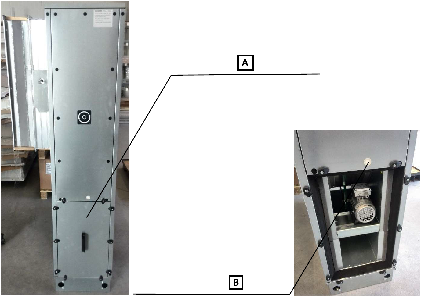
A: Chamber service panel for access to the heat recovery unit drive. The panel can be removed using a 5.0 mm Allen key.
B: The chamber is fitted as standard with a cable gland for connecting the heat recovery unit drive.
¶ COMMISSIONING
¶ TASKS BEFORE COMMISSIONING
| __________________ | __________________ | ||
|---|---|---|---|
| Order number: | User: | ||
| Date: | Commissioning technician: | ||
| Project name: | |||
| Serial number: | |||
| Address: | |||
| Date of first start-up: | Position: |
Tasks for the rotary heat recovery chamber
| No. | Service task description | Task performed | Measured or set value | Note | |
|---|---|---|---|---|---|
| YES | NO | ||||
| 1.01 | Check the cleanliness and absence of damage to the heat exchange surface of the rotor. | ||||
| 1.02 | Check the correct setting of the rotor sealing profiles – circumferential and at the rotor dividing plane. | ||||
| 1.03 | Check the tension of the drive belt. | ||||
| 1.04 | Check the free rotation of the rotor. | ||||
| 1.05 | If the rotor is secured for transport, remove the securing elements. | ||||
| 1.06 | Check the cleanliness of rotating and fixed parts that are in contact (carry out careful cleaning, especially removing metal chips and sawdust). | ||||
| 1.07 |
Tasks for the heat recovery chamber – MaR
| No. | Service task description | Task performed | Measured or set value | Note | |
|---|---|---|---|---|---|
| YES | NO | ||||
| 1.08 | Check the installation and connection of the damper actuator (by-pass/mixing) of the plate heat recovery unit according to the installation instructions. | ||||
| 1.09 | Check the installation of the differential pressure switch/digital manometer according to the installation instructions – plate/rotary heat recovery. | ||||
| 1.10 | Check the electrical connection and setting of the differential pressure switch/digital manometer according to the installation instructions – especially the final pressure loss setting (plate/rotary heat recovery). | ||||
| 1.11 | Check the correct electrical connection of the rotor electric motor according to the enclosed documentation and nameplate values. | ||||
| 1.12 | Check the connection of the frequency converter, if included, according to the enclosed documentation. | ||||
| 1.13 | Check the setting of the frequency converter according to the nameplate values of the rotor electric motor. | ||||
| 1.14 | Check the setting of the frequency converter operating frequency according to the technical specification of the unit. | ||||
| 1.15 | Check the connection according to the electromagnetic compatibility requirements in the enclosed documentation, if required. |
Special tasks:
| No. | Service task description | Task performed | Measured or set value | Note | |
|---|---|---|---|---|---|
| YES | NO | ||||
| 1.16 | |||||
| 1.17 | |||||
| 1.18 | |||||
| 1.19 |
| In....................on.................... | |||
| ______________________ | ______________________ | ||
| Stamp and signature of the service technician: | Stamp and signature of the authorised representative of the equipment operator | ||
| ______________________ | ______________________ | ||
| Surname and service technician number in block capitals | Surname of the authorised representative of the operator in block capitals. |
*Enter the value only where a quantity has to be measured.
¶ TASKS DURING COMMISSIONING
¶ TASKS DURING FIRST START-UP
During the first start-up, the following in particular must be checked:
Rotary regenerative heat exchanger:
• Free running of the rotor
• Correct direction of rotation according to the direction arrow; if necessary, swap two phases in the electric motor terminal box
• Sufficient belt tension and no slipping of the drive pulley
• Correct function of the rotor sealing profiles
• Measurement of the current draw of the electric motor — it must not exceed the nameplate values
• The velocity of the handled air flow through the exchanger must not exceed the recommended speed of 4 m/s
• The pressure loss on the supply or extract air side must not exceed the theoretical value specified in the technical specification by more than 15 %
¶ OPERATION AND MAINTENANCE
Detailed operating instructions and maintenance and service procedures are provided in the following paragraphs and in the sections for the individual parts of the unit.
Before starting any interventions or work on the chamber, wait until the exchanger wheel has come to a complete stop. It must also be made impossible for the fan to start automatically or to be started accidentally by another person!
Check the condition and contamination, wheel mobility and lateral clearance, bearing noise, belt tension and the condition of the heat recovery wheel seal.
Also check the condition of the electric motor and gearbox. Remove contamination from the chamber (belt burrs, pulley abrasion, dust) with a vacuum cleaner and wipe the surfaces with a damp cloth.
Remove contamination from the storage mass of the impeller by blowing with air, steam or a hot-water pressure cleaner. In all cases, care must be taken to prevent deformation of the exchanger fins. For this reason, high-pressure equipment, whether using water or air, must not be used for cleaning. Always direct the water or air jet perpendicular to the storage surface of the exchanger.
Check for any slipping of the belt driving the heat recovery wheel.
Check the position and condition of the movable seal of the heat recovery wheel and make any necessary corrections in areas where the seal is farther away from the wheel. In all cases, direct contact between the wheel and the seal must be prevented.
For the gearbox and electric motor, check bearing noise, any excessive heating, vibrations and the integrity of the conductive bonding to the chamber frame. During maintenance, measure the motor current and check the voltage. Check the fastening of the electric motor to the tensioning base and all bolted connections on the belt tensioning device.
¶ SERVICE AND MAINTENANCE TASK INTERVALS
| SERVICE AND MAINTENANCE TASKS | ||||||||
|---|---|---|---|---|---|---|---|---|
| Inspection task | Unit in operation Y/N* | Service/remedial action | Intervals (months) | |||||
| ROTARY REGENERATIVE HEAT RECOVERY UNIT | 1 | 3 | 6 | 12 | ||||
| 01. | Check that the heat exchange surface of the rotor is not damaged. | N | repair/replacement | ✓ | ||||
| 02. | Check the cleanliness of the heat exchange surface of the rotor. | N | cleaning | ✓ | ||||
| 03. | Check the free rotation of the rotor. | N | repair/replacement | ✓ | ||||
| 04. | Check the tension of the rotor drive belt. | N | repair/cleaning | ✓ | ||||
| 05. | Check the condition and correct setting of the rotor sealing elements – circumferential and transverse seals. | N | repair/replacement | ✓ | ||||
| 06. | Check the condition of the drive electric motor connection – tightening of cables in the terminal box. | N | repair | ✓ | ||||
| 07. | Check the condition and function of the equipment at minimum and maximum speeds. | N | repair/replacement | ✓ | ||||
| 08. | Check the max. air flow velocity of 4 m/s across the exchanger. | Y | repair/replacement | ✓ | ||||
| 09. | Check the max. exchanger pressure loss of 250 Pa or max. +15 % compared with the value specified in the technical specification. | Y | repair/replacement | ✓ |
* unit operating status when the inspection is performed