¶ EVAPORATOR CHAMBER
¶ IDENTIFICATION, ASSEMBLY AND INSTALLATION
The chamber contains a finned evaporator designed for refrigerant (R-410A, R-407A and others) as the heat transfer medium.
The chamber is fitted with the evaporator and, if applicable, with a condensate droplet eliminator as standard at the factory.
The evaporator chamber is fitted as standard at the factory with a tray for draining condensate from the evaporator surface. The outlet is fitted with a DN32 stainless steel pipe for connecting the trap.
Installation of the trap on the positive-pressure or negative-pressure side is described in Section 5.26 INSTALLATION OF TRAPS.
The evaporator connections are marked according to the number of circuits IN1/OUT1, IN2/OUT2 etc. for correct connection of the condensing unit; see the following figure.
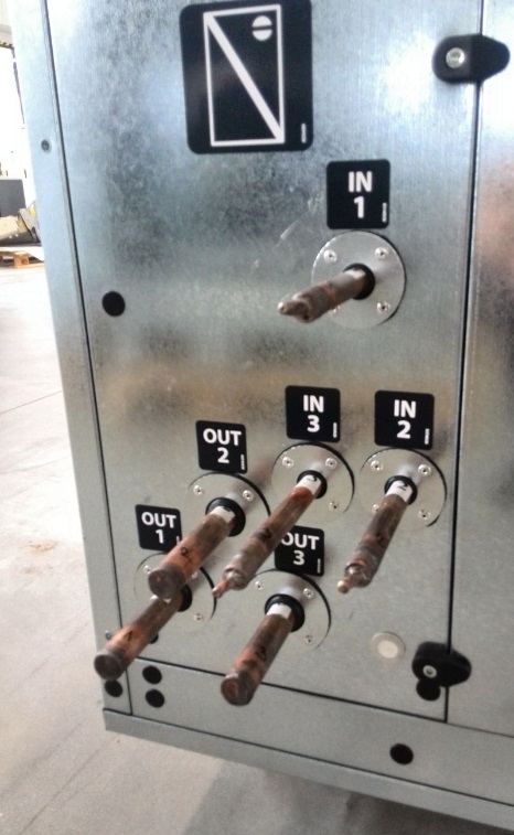
The inlet and outlet connections of the heat exchanger are made of copper, are brazed and are prepared for the installation of refrigeration piping. The heat exchanger is pressure-tested during manufacture and is filled with nitrogen at the factory.
The distributor for injecting refrigerant into the evaporator is located inside the chamber behind a fixed panel. Access to the distributor or to the piping for fitting a temperature sensor, if required by the condensing unit, is possible from the droplet eliminator side after removing its service panel and sliding out the eliminator; see the following figure.
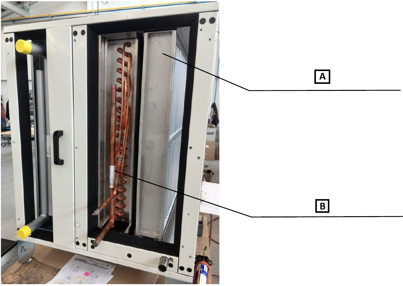
A: Slide-out droplet eliminator
B: Refrigerant distributor located behind the fixed panel
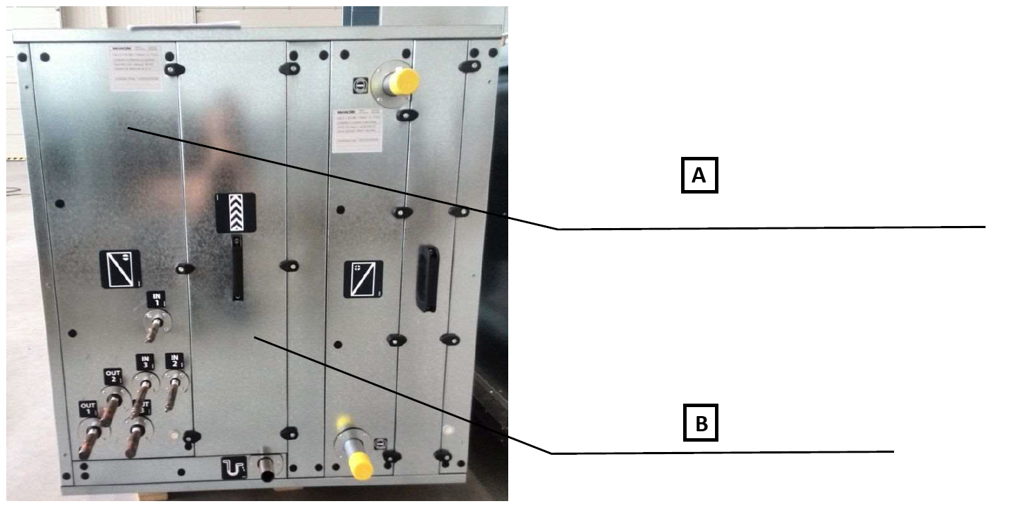
A: Fixed evaporator panel. The panel can be removed after removing the cover plugs and unscrewing the self-tapping screws using a Phillips PH2 bit.
B: Service panel of the droplet eliminator. The panel can be removed using a 5.0 mm Allen key.
The condensing unit is not included in the delivery. Installation may only be carried out by a qualified refrigeration technician authorised to work with refrigerants and in accordance with the condensing unit manufacturer's instructions.
If the MaR measurement and regulation system is part of the delivery, the electrical connection of the condensing unit to the MaR system is specified in the enclosed documentation “Measurement and Regulation of MANDÍK AHUs”.
¶ COMMISSIONING
¶ TASKS BEFORE COMMISSIONING
| __________________ | __________________ | ||
|---|---|---|---|
| Job number: | User: | ||
| Date: | Commissioning party: | ||
| Project name: | |||
| Serial number: | |||
| Address: | |||
| Date of first start-up: | Position: |
Tasks for heat exchanger chambers
| Number | Description of service task | Task performed | Measured or set value | Note | |
|---|---|---|---|---|---|
| YES | NO | ||||
| 1.01 | Check the cleanliness of the heat transfer surface of the heat exchanger and whether it is undamaged. | ||||
| 1.02 | Check the correct connection of inlets/outlets according to the markings on the chamber. | ||||
| 1.03 | Check the circuit tightness by a pressure test. | ||||
| 1.04 | Check that the connections are installed so that thermal expansion of the pipes does not cause excessive loading of the connections. | ||||
| 1.05 | Check the loading of the heat exchanger connections – no components of the cooling source system (piping, expansion valve, etc.) may load the heat exchanger connections. | ||||
| 1.06 | Check that the droplet eliminator is intact, if included. | ||||
| 1.07 | Check installation of the trap according to the assembly instructions, if the chamber is equipped with one. |
Tasks for evaporator chambers – MaR
| Number | Description of service task | Task performed | Measured or set value | Note | |
|---|---|---|---|---|---|
| YES | NO | ||||
| 1.17 | Check installation and, if applicable, the electrical connection of the expansion valve. | ||||
| 1.18 | Check the electrical connection of the condensing unit according to the enclosed documentation. | ||||
| 1.19 | Check the installation and connection of the evaporator temperature sensors and, if applicable, pressure sensors according to the requirements of the condensing unit manufacturer. | ||||
| 1.20 | |||||
| 1.21 | |||||
| 1.22 |
Special tasks:
| Number | Description of service task | Task performed | Measured or set value | Note | |
|---|---|---|---|---|---|
| YES | NO | ||||
| 1.23 | |||||
| 1.24 | |||||
| 1.25 | |||||
| 1.26 |
| At....................on.................... | |||
| ______________________ | ______________________ | ||
| Stamp and signature of the service technician: | Stamp and signature of the authorised representative of the equipment operator | ||
| ______________________ | ______________________ | ||
| Surname and number of the service technician in block capitals | Surname of the authorised representative of the operator in block capitals. |
*Enter the value only if a quantity has to be measured.
¶ TASKS DURING COMMISSIONING
¶ TASKS DURING FIRST START-UP
During first start-up, in particular the following is checked:
Evaporator:
• Tightness of the refrigerant circuit
• Check of the circuit parameter values (pressures, temperatures) in individual sections (high-pressure section, low-pressure section)
• Check of the functionality of individual circuit components (compressor, expansion valve, condensing unit fan, ...)
• Measurement of compressor current consumption -- it must not exceed the nameplate data
• Check of the refrigerant condition
• Correct function of the condensate drain trap (height, filled with water)
¶ OPERATION AND MAINTENANCE
Detailed operating instructions and maintenance and service procedures are given in the following sections and further in the individual parts of the unit.
When filling, draining and venting the heat exchanger, contact between unprotected skin and the heat transfer medium must be prevented. If additives or complete ready-made mixtures are used in the cooling system, the manufacturer's information on the use and handling of these substances must be observed.
For heat exchangers, check contamination, tightness and possible damage. Remove contamination by blowing with air, steam or a hot-water pressure cleaner against the direction of airflow. In all cases, care must be taken to avoid deformation of the heat exchanger fins; for this reason, high-pressure equipment, whether water or air, should not be used for cleaning.
Regularly check the tightness of the refrigerant circuit, the condition of the pipe insulation and the fastening of the connections. Also monitor the condition and cleanliness of the evaporator fins – dirty fins reduce output and may cause the heat exchanger to freeze.
Before the cooling season, check the functionality of the regulation, fans and temperature sensors, and, if applicable, the frost protection.
During longer shutdowns of the equipment, it is necessary to ensure that the refrigerant circuit is hermetically sealed and that moisture does not condense on the heat exchanger. It is recommended to dry the heat exchanger and protect it against dust.
For coolers, also check the condition and function of the condensate drain trays, the unobstructed drainage from the tray, and the condition and function of the trap; clean and add water as necessary. Before winter, check the functionality of anti-freeze measures for condensate drains (if they are in operation also during the winter period and there is a risk of freezing). Also check for deposits and the condition and cleanliness of the droplet eliminator; slide it out and clean it if necessary.
¶ SERVICE AND MAINTENANCE TASK INTERVALS
| SERVICE AND MAINTENANCE TASKS | ||||||||
|---|---|---|---|---|---|---|---|---|
| Inspection task | Unit in operation Y/N* | Service/remedy method | Intervals (months) | |||||
| EVAPORATOR | 1 | 3 | 6 | 12 | ||||
| 01. | Check that the heat transfer surface of the heat exchanger is undamaged. | N | repair/replacement | ✓ | ||||
| 02. | Check the cleanliness of the heat transfer surface of the heat exchanger. | N | cleaning | ✓ | ||||
| 03. | Check the condition and cleanliness of the condensate droplet eliminator. | N | repair/cleaning | ✓ | ||||
| 04. | A comprehensive check of the condition and function of the refrigerant circuit (tightness, expansion valve, condensing unit, refrigerant condition, …) must always be carried out by a qualified refrigeration technician authorised to work with refrigerants. | N | repair/replacement | ✓ | ||||
| 05. | Check the cleanliness and unobstructed flow of the condensate drain. | N | cleaning/repair | ✓ | ||||
| 06. | Check the condition of the condensate drain trap and that it is filled with water. | N | repair | ✓ |
* unit operating status when the check is carried out