¶ FAN CHAMBER WITH FREE-RUNNING IMPELLER
¶ IDENTIFICATION, ASSEMBLY AND INSTALLATION
The chamber contains a fan assembly – a free-running impeller with backward-curved blades and an electric motor.
The fan chamber is normally fitted with the assembly at the factory.
The assembly is statically and dynamically balanced (vibration severity below 2.8 mm/s according to DIN ISO 14694), therefore no additional balancing is required.
Two types of electric motors are used to drive the fans:
• Three-phase asynchronous squirrel-cage motors are supplied with 3x400V/50Hz voltage. If the motor nameplate states 230V D / 400V Y 50 Hz, the motor is connected in star; if it states 400V D / 690V Y 50 Hz, the motor is connected in delta. All necessary information is stated on the motor nameplate and on the terminal box cover. It is recommended to supply the motors from a frequency converter set according to the electric motor nameplate values, with a sufficient run-up time. When the motor is supplied from a frequency converter, electromagnetic interference may occur in the supply cables. Therefore, shielded cables must be used to connect the motor and the frequency converter, and the instructions contained in the technical documentation of the frequency converter must be observed.
• EC motors are electronically commutated three-phase synchronous motors. They have an integrated voltage converter, which controls the motor speed by means of an electrical signal. All control and protection functions are integrated in the control unit located in the fan motor – only the power supply 1~230V/50Hz or 3~400V/50Hz and the 0-10V control signal are connected. All necessary information is stated on the motor nameplate. EC motors achieve relatively high performance and dynamics despite their small dimensions and have quiet and smooth operation.
When the electric motor is supplied from a frequency converter, the thermistor terminals must be connected to the appropriate terminals of the frequency converter, provided that the frequency converter is correctly set.
The frequency converter parameter settings are stated in the documentation enclosed with the unit.
The wiring diagram of AC and EC electric motors is shown on the covers of the electric motor terminal boxes. Typical wiring of AC and EC electric motors is shown in Appendix C. ELECTRICAL WIRING OF ELECTRIC MOTORS.
If a measurement and regulation system is supplied, the specific wiring of the electric motors or frequency converters is stated in the enclosed documentation “Measurement and Regulation of MANDÍK AHU”.
If included in the delivery and based on the requirement, the chamber is normally fitted with a service safety switch. Otherwise, the recommended installation is stated in the document “Installation and Operation Manual for the Measurement and Regulation System”.
The electrical wiring diagram of the service switch is stated in APPENDIX J. ELECTRICAL WIRING OF THE SERVICE SWITCH / SERVICE SWITCH WITH FREQUENCY CONVERTER.
If electrical wiring of the measurement and regulation system is required according to Directive 2004/108/EC – electromagnetic compatibility (residential environment – immunity and emissions, industrial environment – immunity and emissions), the recommended procedures are stated in Appendix D. ELECTRICAL WIRING ACCORDING TO DIRECTIVE 2004/108/EC – EMC of this manual.
For routing the power conductors, the fan chamber is normally equipped with cable glands for connecting the electric motor and the frequency converter, with dimensions according to the given electrical input of the electric motor.
The fan chamber, in the configuration of unit type M40/P40 and larger, must be fitted with a safety element to prevent excessive overpressure downstream of the fan chamber and thus prevent damage to the chambers or injury to persons moving near the fan chamber or other chambers downstream of it.
A differential pressure gauge, for example HK-Instruments PS4500, with a sufficient degree of protection (IP65) if installed outdoors, is recommended as the safety element.
The differential pressure gauge must be connected to the measurement and regulation system so that the fan is switched off when the switching value is exceeded (contact opening). The switching pressure value must be set to + 2000 Pa (i.e. overpressure downstream of the fan relative to atmospheric pressure).
If the unit is ordered with the Mandík measurement and regulation system, the differential pressure gauge is part of the delivery and part of the drawing documentation of the measurement and regulation system. Depending on the selected method of attaching/installing the measurement and regulation system components, the pressure gauge is either packed with the other elements of the measurement and regulation system or mounted on the chamber.
The electrical wiring diagram is stated in APPENDIX I. ELECTRICAL WIRING OF THE SAFETY DIFFERENTIAL PRESSURE GAUGE FOR HIGH FAN OVERPRESSURE
The fan chamber is normally fitted with a pressure tapping point for easy installation of the differential pressure gauge. The installation is shown in the following figure.
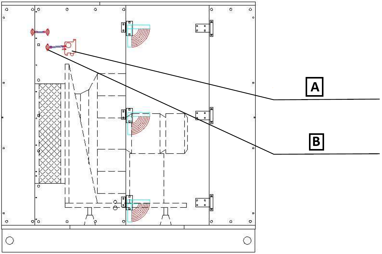
A: Safety differential pressure gauge against fan overpressure
B: Pressure tapping probe for the differential pressure gauge
¶ COMMISSIONING
¶ TASKS BEFORE COMMISSIONING
List of service tasks before starting the Mandík air handling unit
| __________________ | __________________ | ||
|---|---|---|---|
| Order number: | User: | ||
| Date: | Commissioning technician: | ||
| Project name: | |||
| Serial number: | |||
| Address: | |||
| First start-up date: | Position: |
Tasks for fan chambers – Free-running impeller
| No. | Description of service task | Task performed | Measured or set value | Note | |
|---|---|---|---|---|---|
| YES | NO | ||||
| 1.01 | Check that the assembly is installed in accordance with the technical specification of the unit. | ||||
| 1.02 | Check the correct mechanical installation of the fan (tightening of all screws, etc.). | ||||
| 1.03 | Check the condition of the assembly anti-vibration mounts – no deformation, misalignment, etc. | ||||
| 1.04 | Check the integrity of the fan flexible insert. | ||||
| 1.05 | Check free rotation of the impeller. | ||||
| 1.06 | Check cleanliness of the impeller and the chamber. | ||||
| 1.07 | Check the condition of the earthing connections. | ||||
| 1.08 | Check the correct direction of rotation according to the direction arrow – by briefly switching on the electric motor. | ||||
| 1.09 | Check fan operation without excessive noise. Otherwise, the assembly must be statically and dynamically balanced. | ||||
| 1.10 | The motor and fan assembly must not be operated in the range of resonance speeds or their multiples. During commissioning, these resonance speeds must be identified and operation at them must subsequently be eliminated by setting the frequency converter. | ||||
| 1.11 | |||||
| 1.12 | |||||
| 1.13 |
Tasks for fan chambers – Measurement and regulation
| No. | Description of service task | Task performed | Measured or set value | Note | |
|---|---|---|---|---|---|
| YES | NO | ||||
| 1.14 | Check the correct electrical wiring of the assembly electric motor according to the enclosed documentation and the electric motor nameplate values. | ||||
| 1.15 | Before first starting the fan, the insulation resistance of the electric motor must be measured to prevent possible damage to it. | ||||
| 1.16 | Check the wiring of the frequency converter, if included, according to the enclosed documentation. | ||||
| 1.17 | Check the frequency converter settings according to the nameplate values of the assembly electric motor. | ||||
| 1.18 | Check the operating frequency setting of the frequency converter according to the technical specification of the unit. | ||||
| 1.19 | Check the wiring according to electromagnetic compatibility requirements in accordance with the enclosed documentation, if required. | ||||
| 1.20 | Check the connection of pressure probes for differential pressure measurement according to the installation instructions. | ||||
| 1.21 | Check the connection and verify the functionality of the safety differential pressure gauge against excessive overpressure. |
Special tasks:
| No. | Description of service task | Task performed | Measured or set value | Note | |
|---|---|---|---|---|---|
| YES | NO | ||||
| 1.24 | |||||
| 1.25 | |||||
| 1.26 | |||||
| 1.27 |
| In....................on.................... | |||
| ______________________ | ______________________ | ||
| Stamp and signature of the service technician: | Stamp and signature of the authorised representative of the equipment operator | ||
| ______________________ | ______________________ | ||
| Surname and number of the service technician in block letters | Surname of the authorised representative of the operator in block letters. |
*Enter the value only if it is necessary to measure a quantity.
¶ TASKS DURING COMMISSIONING
When the unit is started for the first time, the following must be checked:
The fan must not be started when shut-off or control dampers are closed. Pressure surges occurring during functional tests of fire or other dampers with a short actuation time to the closed position must be avoided.
¶ TASKS DURING FIRST START-UP
During the first start-up, the following in particular is checked:
• Measurement of the electric motor current consumption — it must not exceed the nameplate
values
¶ BALANCING THE AIR FLOW RATES OF THE UNIT
During the first start-up and after carrying out the tasks from the previous chapter TASKS DURING COMMISSIONING, the air flow rate of the unit must be checked according to the technical specification, or the fan speed/frequency must be adjusted.
CPV and CPX units:
-Quick adjustment of the supply/extract fan output is described in Appendix WEB/HMI CONTROLLER POL871.
-Starting the unit into operation (operating mode) is described in Appendix HMI CONTROLLER POL871 or CONTROLLER POL822
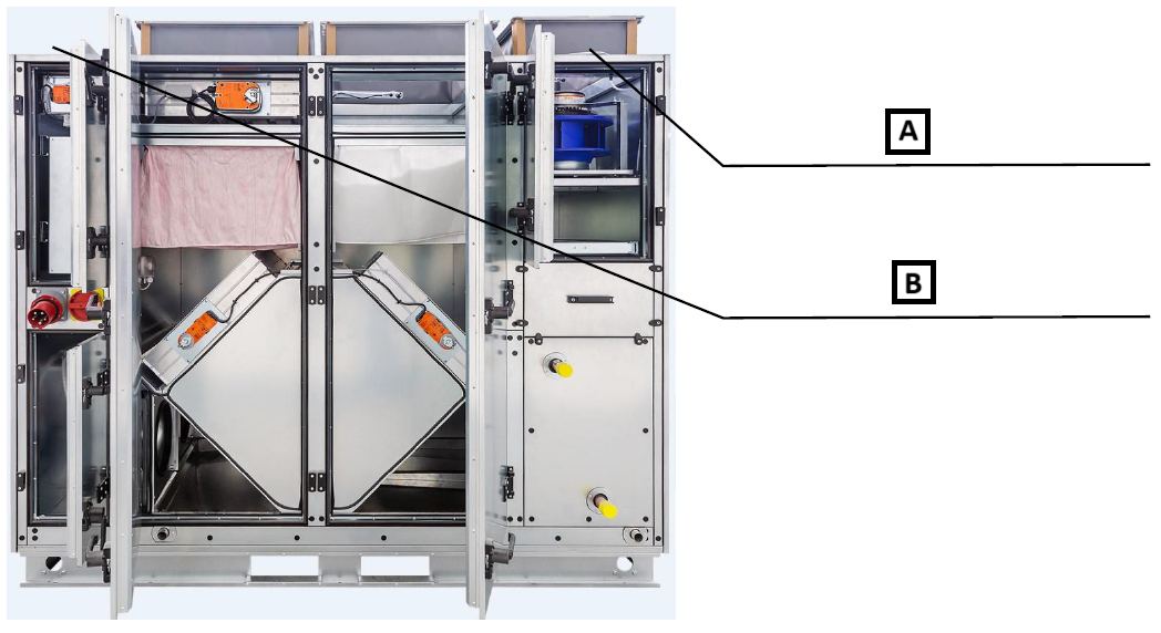
For measuring the fan air flow rate, or rather its differential pressure, the fan chamber is equipped with pressure tapping probes; see the following figure.
A: Sticker with k-factors of the individual fan impellers for calculating the air flow rate [m³/h] on the basis of the measured differential pressure [Pa].
B: Probes for measuring the differential pressure of the fan
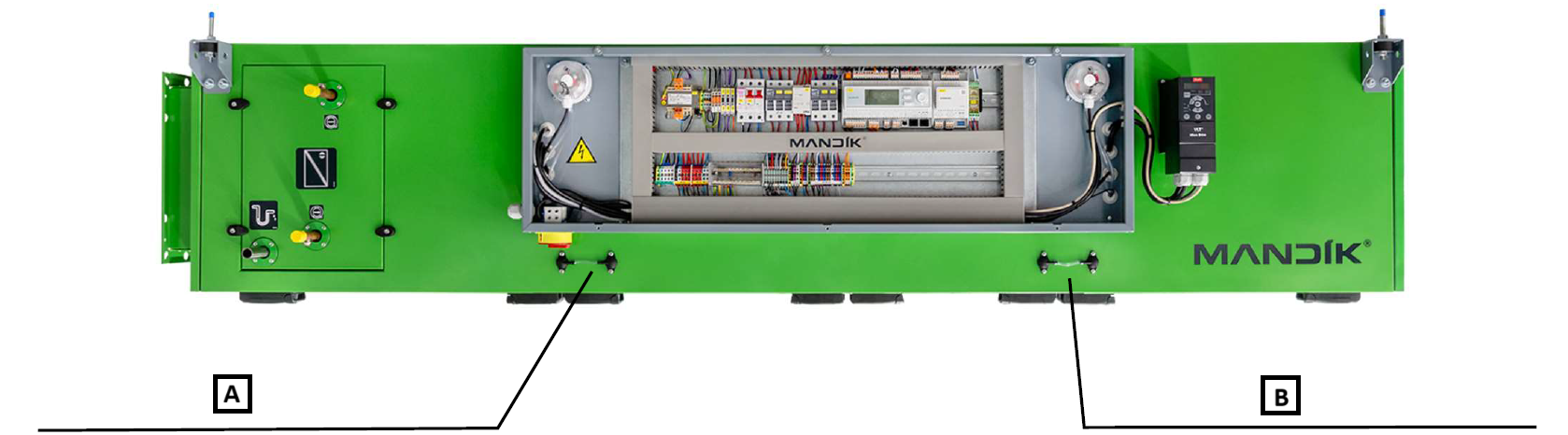
CPV and CPX units:
A: Probe of the supply fan for measuring differential pressure.
B: Probe of the extract fan for measuring differential pressure.
A: Probe of the supply fan for measuring differential pressure.
B: Probe of the extract fan for measuring differential pressure.
AIR FLOW RATE CALCULATION:
After measuring the differential pressure [Pa], the air flow rate is calculated according to the k-factor of the given fan and the formula stated on the fan sticker.
Otherwise, the air flow rate can be calculated as follows:
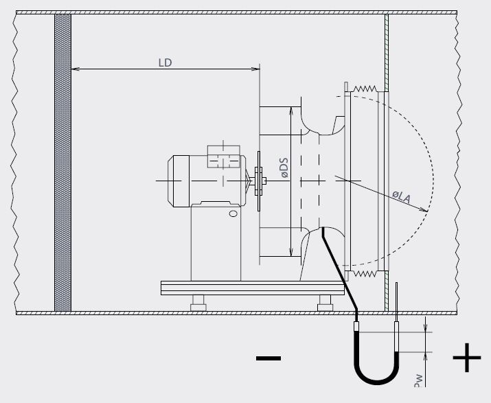
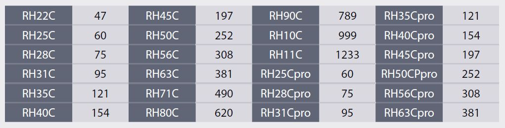
K-factors of free-running fan impellers. Valid for air density 1.2 .
Formula for calculating the air flow rate .
k = k-factor (table above), = measured pressure difference [Pa]
To eliminate the deviation between the measured air flow rate and the required air flow rate specified by the project (technical specification), the operating frequency [Hz] of the fan is adjusted on the frequency converter. Increasing the frequency = increasing the air flow rate and vice versa.
When increasing the load, the current drawn by the fan electric motor must be checked. The electric motor values must not exceed its nameplate values.
When balancing is carried out, all dampers must be in the maximum open position.
If the required air flow rate cannot be achieved, or if the operating frequency has been increased/decreased very significantly, this is an indication that the unit should be checked (internal contamination, foreign local pressure resistances) or the duct route should be checked (foreign local pressure resistances, the designed external pressure loss does not correspond to the actual ductwork), etc.
The unit balancing record must be entered in the relevant protocol.
The results of the measured values are satisfactory if the deviation between the measured values and the values in the technical specification of the unit does not exceed ±10%.
For a supply and extract unit, the air flow rates must always be balanced according to the pressure conditions given by the project or by the type of operation of the air-conditioned space — balanced-pressure/overpressure/underpressure ventilation.
The balancing protocol must contain the following information:
• Identification of the equipment (order number, serial number, position in the project)
• Details of the person performing the balancing, including signature or stamp
• Nominal parameters of the equipment (air flow rates, current load of fan electric motors — nameplate values)
• Measuring instruments used
• Functional diagram of the equipment, including a diagram of the duct routes with dimensions and a description of their parts (inserted elements — silencers, filters, etc., control dampers, branches, elbows, etc.)
• List and values of measuring points
• Time schedule of the balancing process (unit start, unit stop)
• Climatic conditions during equipment operation (inlet/outlet temperatures and humidity of supply and extract air)
• Record of operation and condition of individual parts of the unit listed in paragraph 7.1
• Record of detected faults
• Record of test evaluation (result, date, etc.)
• Table of measured and set values of individual fans (frequency, air flow rates, currents)
¶ OPERATION AND MAINTENANCE
Before starting any interventions or work on the chamber, wait until the fan impeller has come to a complete stop. It is also necessary to prevent spontaneous start-up or accidental start-up of the fan by another person. The safety switch on the front or side of the unit is intended for this purpose (according to the specific layout of the unit).
On the fan, check the cleanliness of the free-running impeller. Remove any coarse dust with a vacuum cleaner and wipe fine dust with a damp cloth.
Keeping the fan impeller clean is very important, especially in terms of maintaining the best possible balance. Any damage to painted surfaces or traces of corrosion must be treated and repaired with a suitable coating.
Regularly check for any imbalance (vibrations), attachment of the impeller to the hub and attachment of the hub to the electric motor shaft. Also check the width of the gap between the free-running impeller and the fan inlet, and the tightening of all bolted connections on the motor and fan assembly. On the electric motor, check vibrations, bearing noise, possible excessive heating, tightening of the terminals in the terminal box and integrity of the conductive bonding to the chamber frame.
During maintenance, measure the motor current and check the voltage and phase symmetry. Repair any damage to surfaces. Check correct fastening of the electric motor to the base and all bolted connections on the fan assembly base. Also check the functionality of the rubber vibration dampers under the assembly and their anchoring. The periodic inspection also includes checking the tightness and integrity of the flexible sleeve on the fan suction side and cleaning it.
If the fan is equipped with a safety differential pressure gauge, check its correct function by a verification test using suitable overpressure in the chamber.
¶ SERVICE AND MAINTENANCE TASK INTERVALS
Detailed operating instructions and maintenance and service procedures are given in the following paragraphs and further in the individual parts of the unit.
| SERVICE AND MAINTENANCE TASKS | ||||||||
|---|---|---|---|---|---|---|---|---|
| Inspection task | Unit in operation Y/N* | Service/remedy method | Intervals (months) | |||||
| FANS WITH FREE-RUNNING IMPELLER | 1 | 3 | 6 | 12 | ||||
| 01. | Check cleanliness and condition of the impeller and the internal part of the chamber. | N | cleaning | ✓ | ||||
| 02. | Check free running of the impeller. | N | repair | ✓ | ||||
| 03. | Tighten cables in the electric motor terminal box. | N | repair | ✓ | ||||
| 04. | Check excessive vibration of the assembly – the assembly must have no visible vibrations. | Y | repair | ✓ | ||||
| 05. | For AHU: Check the integrity of the fan flexible insert. | Y | replacement | ✓ | ||||
| 06. | For AHU: Check the condition of the assembly vibration isolator. | Y | repair | ✓ | ||||
| 07. | For AHU: Check the function of the safety differential pressure gauge against excessive overpressure (if the fan is equipped with it). | Y | replacement | ✓ |
* operating status of the unit during the inspection