¶ FILTER CHAMBER
¶ IDENTIFICATION, ASSEMBLY AND INSTALLATION
¶ G2-F9 / GREASE FILTER CHAMBER
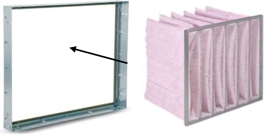
The chamber contains filter inserts of the pre-filter type (G2-G4), bag filter inserts (G4-F9), or grease filters.
The filter chamber is normally fitted with filter inserts at the factory.
If the delivery of uninstalled filters has been agreed, the filters are packed in a cardboard box placed in one of the unit chambers or on a separate pallet. This depends on the size of the box.
The grease filter chamber can, on request, be fitted with a tray for collecting grease and fat. The outlet is fitted with a stainless-steel DN32 pipe for pipework installation.
On request, if included in the delivery, the chamber is fitted with a differential pressure switch or a digital differential pressure gauge. Otherwise, the recommended installation is specified in the document “Installation and Operation Manual for the Measurement and Regulation System”.
The recommended final pressure loss setting for the individual filter classes is specified in the appendix RECOMMENDED FINAL PRESSURE LOSSES OF FILTERS.
On request, if included in the delivery, the chamber can be fitted with an inclined-tube liquid manometer for visual inspection.
Two types of filter insert fixing are used. The types and procedure for installing filter inserts in the filter chamber are as follows:
¶ 1) Guide rails with clamping - with sliding catch
For units up to a clear width of 2500 mm. The inserts are always inserted from the clean side.
The filter insert gasket is already installed at the factory on the filter frame. It is therefore not necessary to apply a gasket to the filter inserts themselves, even during replacement.
Releasing the filter inserts using the sliding catch –> pull towards you .
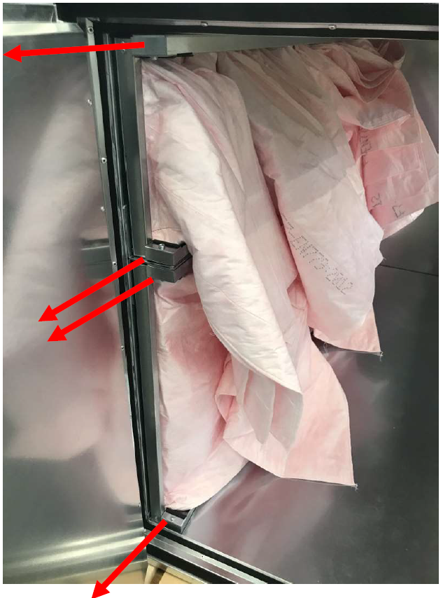
¶ 2) Guide rails with clamping - with lever
For units up to a clear width of 2500 mm. The inserts are always inserted from the clean side.
The filter insert gasket is already installed at the factory on the filter frame. It is therefore not necessary to apply a gasket to the filter inserts themselves, even during replacement.
Releasing the filter inserts using the lever –> push away from you .
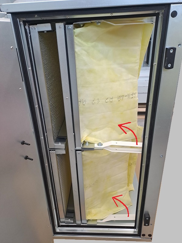
¶ 3) Mounting frames
For units with a clear width above 2500 mm or on the basis of a requirement from the design software.
The inserts are always inserted from the dirty side and in such a way that the insert frame presses against the mounting frame. See the following figure for the insertion direction.
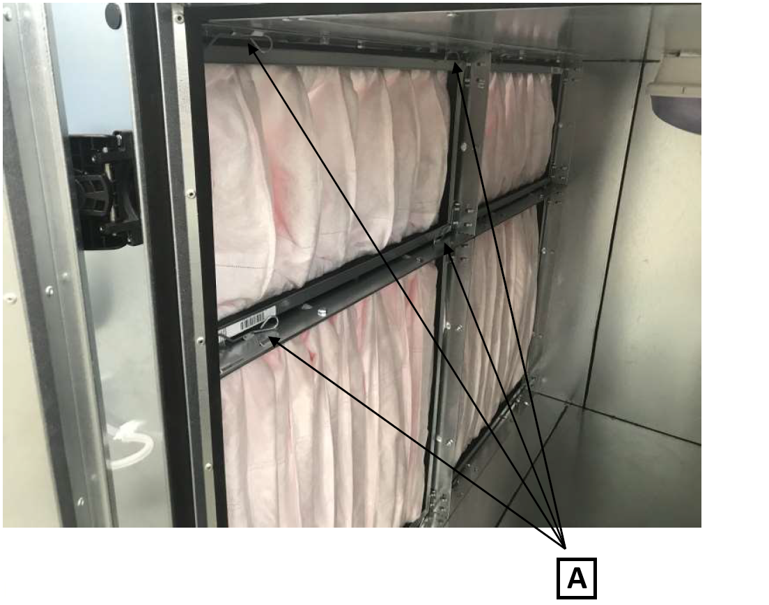
A: The filter inserts are clamped into the mounting frames using a clamping mechanism (in each corner of the mounting frame).
The filter insert gasket is already installed at the factory on the mounting frames. It is therefore not necessary to apply a gasket to the filter inserts themselves, even during replacement.
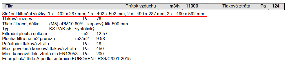
The filter configuration for type sizes M/M+, P/P+ and T/T+ and for dynamic (custom) cross sections is specified in the project technical specification, in the filter section:
¶ ACTIVE CARBON FILTER CHAMBER
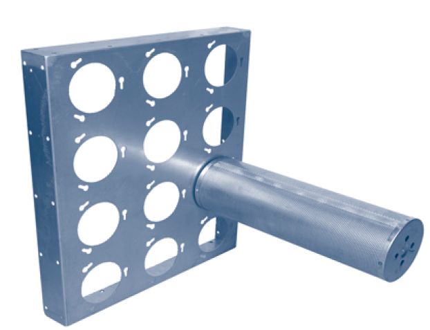
The chamber contains adsorption cartridges filled with granular active carbon. The cartridge lengths can be 450 or 625 mm. The cartridges are fixed in the mounting frame using a bayonet system, see the figure:
Active carbon filter cartridges are transported separately. They are installed in the chambers during final assembly after the entire air handling system has been cleaned.
¶ COMMISSIONING
¶ TASKS BEFORE COMMISSIONING
| __________________ | __________________ | ||
|---|---|---|---|
| Order number: | User: | ||
| Date: | Commissioning technician: | ||
| Project name: | |||
| Serial number: | |||
| Address: | |||
| Date of first start-up: | Position: |
Tasks for filter chambers - G2-F9 / grease filters (bag and panel filters) - guide rail
| No. | Description of service task | Task performed | Measured or set value* | Note | |
|---|---|---|---|---|---|
| YES | NO | ||||
| 1.01 | Check that filter inserts of the same filter class according to the unit technical specification are installed. | ||||
| 1.02 | Check that filter inserts are installed according to the prescribed configuration in accordance with the installation instructions. | ||||
| 1.03 | Check the sealing between filter inserts according to the installation instructions. | ||||
| 1.04 | Check that the filter inserts are firmly fixed in the holders. | ||||
| 1.05 | Check the cleanliness and integrity of the filter inserts. | ||||
| 1.06 |
Tasks for filter chambers - G2-F9 / grease filters (bag and panel filters) - mounting frames
| No. | Description of service task | Task performed | Measured or set value* | Note | |
|---|---|---|---|---|---|
| YES | NO | ||||
| 1.07 | Check that filter inserts of the same filter class according to the unit technical specification are installed. | ||||
| 1.08 | Check that filter inserts are installed according to the prescribed configuration in accordance with the installation instructions. | ||||
| 1.09 | Check the sealing between the frame seating surface and the filter insert frame. | ||||
| 1.10 | Check that the filter inserts are firmly fixed in the mounting frames. | ||||
| 1.11 | Check the cleanliness and integrity of the filter inserts. | ||||
| 1.12 |
Tasks for filter chambers - G2-F9 / grease filters (bag and panel filters) - active carbon
| No. | Description of service task | Task performed | Measured or set value | Note | |
|---|---|---|---|---|---|
| YES | NO | ||||
| 1.13 | Check that filter cartridges are installed according to the unit technical specification. | ||||
| 1.14 | Check the secure fixing of the filter cartridges. | ||||
| 1.15 |
Tasks for filter chambers - Measurement and Regulation
| No. | Description of service task | Task performed | Measured or set value | Note | |
|---|---|---|---|---|---|
| YES | NO | ||||
| 1.16 | Check the installation of the differential pressure switch / digital manometer according to the installation instructions. | ||||
| 1.17 | Check the electrical connection and setting of the differential pressure switch / digital manometer according to the installation instructions - especially the setting of the final filter pressure loss. | ||||
| 1.18 | |||||
| 1.19 | |||||
| 1.20 | |||||
| 1.21 | |||||
| 1.22 | |||||
| 1.23 |
Special tasks:
| No. | Description of service task | Task performed | Measured or set value | Note | |
|---|---|---|---|---|---|
| YES | NO | ||||
| 1.24 | |||||
| 1.25 | |||||
| 1.26 | |||||
| 1.27 |
| In....................on.................... | |||
| ______________________ | ______________________ | ||
| Stamp and signature of the service technician: | Stamp and signature of the authorised representative of the equipment operator | ||
| ______________________ | ______________________ | ||
| Surname and number of the service technician in block letters | Surname of the authorised representative of the operator in block letters. |
*Enter the value only if it is necessary to measure a quantity.
¶ TASKS DURING COMMISSIONING
¶ TASKS DURING FIRST START-UP
During the first start-up, the following in particular is checked:
After the first commissioning, all inlet filters must be cleaned or replaced with new ones if necessary.
¶ OPERATION AND MAINTENANCE
Dust deposited on the filter insert may cause allergic reactions on the skin, mucous membranes and eyes, or breathing difficulties. Therefore avoid contact with the captured dust. Protective clothing and, if necessary, protective equipment (respiratory mask, etc.) must be used during maintenance and filter insert replacement!
For the filter chamber, check the cleanliness of the chamber; remove any coarse dust with a vacuum cleaner and wipe fine dust with a damp cloth. Also check the clogging and tightness of the entire filter insert. When replacing filters, avoid contaminating the chambers or new filter inserts with deposited dust.
¶ Bag and panel filters
Depending on the filter class used and their replacement interval, at least one set of spare filters must always be added to stock in time, while ensuring that their prescribed maximum storage period is not exceeded. We recommend determining the filter replacement interval based on observations during trial operation of the unit. Depending on local conditions, this interval may then be shorter or longer than the regular maintenance interval. However, the maximum permitted final pressure loss for the filter insert type used and the time interval of 12 months between individual replacements (applies to the first filtration stage) must never be exceeded. For the second and subsequent filtration stages, as well as filters in the exhaust sections of units, this period may be determined individually but should not exceed 24 months. As a rule, all filters in the entire filter insert are replaced at the same time; replacement of individual filters is permissible only if they are damaged.
¶ Active carbon filters
In operations where harmless odours are separated by an active carbon filter, the functionality of the filter can be checked sensorily by smell. In cases where odourless, toxic or otherwise harmful substances are separated, the saturation of the active carbon and the remaining service life of the filters can only be determined by a laboratory test carried out by the manufacturer of the filter cartridges. Based on this test, the replacement interval for active carbon cartridges can then be determined. When determining the replacement interval, however, the properties and nature of the separated substances must always be taken into account, especially with regard to their possible health hazards or other hazards.
The recommended final pressure losses of filters are specified in Appendix F.
A different pressure differential switching value can be set manually by adjusting the value on the switching pressure switch of the supply/extract filter. The pressure switches are located under the filters on the side of the chamber for CPV or in the switchboard for CPX, see the following figure.
| A: SUPPLY FILTER | B: SUPPLY PRESSURE SWITCH |
Recommended final filter pressure losses:
- The values are specified in the technical specification for the unit, according to the selected filter class and filter type
¶ SERVICE AND MAINTENANCE TASK INTERVALS
Detailed operating instructions and maintenance and service procedures are specified in the following paragraphs and in the individual parts of the unit.
| SERVICE AND MAINTENANCE TASKS | ||||||||
|---|---|---|---|---|---|---|---|---|
| Inspection task | Unit in operation Y/N* | Service/remedy method | Intervals (months) | |||||
| ACTIVE CARBON FILTERS | 1 | 3 | 6 | 12 | ||||
| 01. | General inspection of contamination, damage and corrosion of all unit parts (external/internal). | N | replacement | ✓ | ||||
| 02. | Check the fixing of filter cartridges in the frame. | N | repair | ✓ | ||||
| 03. | Check the condition of the filter medium - active carbon, by the gravimetric method. | N | reactivation | ✓ |
* operating status of the unit when the inspection is performed
| SERVICE AND MAINTENANCE TASKS | ||||||||
|---|---|---|---|---|---|---|---|---|
| Inspection task | Unit in operation Y/N* | Service/remedy method | Intervals (months) | |||||
| G2-F9 FILTERS, GREASE FILTERS | 1 | 3 | 6 | 12 | ||||
| 01. | Check the pressure loss of filters. | N | value from MaR | ✓ | ||||
| 02. | Check the integrity of the filter medium of filter inserts. | Y | replacement | ✓ | ||||
| 03. | Check the integrity of the sealing profiles of the filter holder and the sealing between filter inserts. | Y | repair | ✓ | ||||
| 04. | Check the setting and function of the differential pressure gauge (switch, digital, inclined tube). | Y | resetting/replacement | ✓ | ||||
| 05. | Check the fixing of pressure probes for measuring filter pressure differential. | Y | repair | ✓ |
* operating status of the unit when the inspection is performed