Each unit that meets the definition of a complete machine is provided with a unit identification plate. The plate contains the manufacturer’s basic identification details, the unit designation, year of manufacture, rated parameters, degree of protection and other information required for safe operation and servicing. Its main purpose is to enable unambiguous identification of the entire equipment.
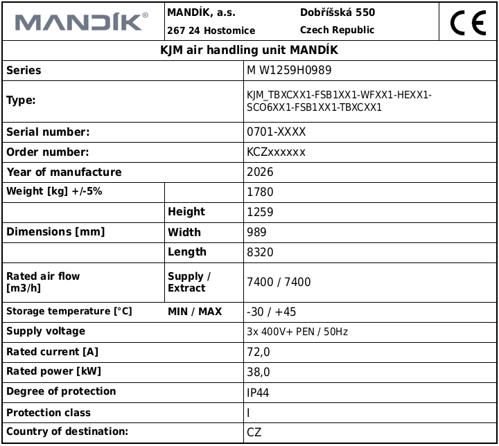 Fig.: Example of a unit identification plate
The code consists of seven characters.
The code identifies the individual unit chambers in the order in which they are arranged, from the unit air inlet to the unit air outlet.
- CODE STRUCTURE: KJM_A-B-C-D-E-F-G-H-I-J-K-L-M-N-O-P-Q-R-S-T
|
|
|
| Letter |
Chamber number |
The parameter value may be |
| A |
1 |
0 / chamber code |
| B |
2 |
0 / chamber code |
| C |
3 |
0 / chamber code |
| D |
4 |
0 / chamber code |
| E |
5 |
0 / chamber code |
| F |
6 |
0 / chamber code |
| G |
7 |
0 / chamber code |
| H |
8 |
0 / chamber code |
| I |
9 |
0 / chamber code |
| J |
10 |
0 / chamber code |
| K |
11 |
0 / chamber code |
| L |
12 |
0 / chamber code |
| M |
13 |
0 / chamber code |
| N |
14 |
0 / chamber code |
| O |
15 |
0 / chamber code |
| P |
16 |
0 / chamber code |
| Q |
17 |
0 / chamber code |
| R |
18 |
0 / chamber code |
| S |
19 |
0 / chamber code |
| T |
20 |
0 / chamber code |
- DESCRIPTION OF INDIVIDUAL CHAMBER CODES:
| Position 1 |
|
Position 2 |
|
Position 3 |
|
Position 4 |
|
Position 5 |
|
Position 6 |
|
Position 7 |
|
| Value |
Meaning of value |
Value |
Meaning of value |
Value |
Meaning of value |
Value |
Meaning of value |
Value |
Meaning of value |
Value |
Meaning of value |
Value |
Meaning of value |
| END PANEL |
|
TYPE |
|
DAMPER |
|
ELEMENT |
|
-- unused -- |
|
TRAY |
|
UNIT AIR STREAM |
|
| T |
END PANEL |
B |
LARGE |
X |
none |
C |
flexible connection |
X |
none |
X |
none |
1 |
Supply-air section |
|
|
S |
SMALL |
O |
outside |
L |
louvre |
|
|
P |
old |
2 |
Extract-air section |
|
|
C |
CIRCULAR |
I |
inside |
D |
straight discharge hood |
|
|
H |
hygienic |
|
|
|
|
|
|
|
|
S |
angled discharge hood |
|
|
|
|
|
|
|
|
|
|
|
|
F |
flange |
|
|
|
|
|
|
|
|
|
|
|
|
X |
none |
|
|
|
|
|
|
|
|
|
|
|
|
W |
blanking panel, full wall in the main cross-section |
|
|
|
|
|
|
|
|
|
|
|
|
U |
mating flange with flange |
|
|
|
|
|
|
|
|
|
|
|
|
G |
hygienic flange |
|
|
|
|
|
|
| Position 1 |
|
Position 2 |
|
Position 3 |
|
Position 4 |
|
Position 5 |
|
Position 6 |
|
Position 7 |
|
| Value |
Meaning of value |
Value |
Meaning of value |
Value |
Meaning of value |
Value |
Meaning of value |
Value |
Meaning of value |
Value |
Meaning of value |
Value |
Meaning of value |
| FAN |
|
TYPE |
|
-- unused -- |
|
TRAY |
|
-- unused -- |
|
-- unused -- |
|
UNIT AIR STREAM |
|
| W |
FAN |
F |
FREE WHEEL |
X |
|
X |
none |
|
|
|
|
1 |
Supply-air section |
|
|
R |
RADIAL |
|
|
P |
old tray |
|
|
|
|
2 |
Extract-air section |
|
|
M |
MINI FREE WHEEL |
|
|
H |
hygienic tray |
|
|
|
|
|
|
| Position 1 |
|
Position 2 |
|
Position 3 |
|
Position 4 |
|
Position 5 |
|
Position 6 |
|
Position 7 |
|
| Value |
Meaning of value |
Value |
Meaning of value |
Value |
Meaning of value |
Value |
Meaning of value |
Value |
Meaning of value |
Value |
Meaning of value |
Value |
Meaning of value |
| FILTER |
|
DESIGN |
|
FILTER CATEGORY |
|
FILTER TYPE |
|
-- unused -- |
|
TRAY |
|
UNIT AIR STREAM |
|
| F |
FILTER |
S |
SEPARATE |
B |
bag filter |
1 |
1" |
X |
|
X |
none |
1 |
Supply-air section |
|
|
1 |
2 stages, first 1" |
P |
panel filter |
2 |
2" |
|
|
P |
old tray |
2 |
Extract-air section |
|
|
2 |
2 stages, first 2" |
F |
grease filter |
3 |
292-360 |
|
|
H |
hygienic tray |
|
|
|
|
4 |
2 stages, first 4" |
C |
carbon filter |
4 |
4" |
|
|
|
|
|
|
|
|
T |
2 filters in 1 mounting frame |
K |
compact filter |
5 |
500 |
|
|
|
|
|
|
|
|
|
|
|
|
6 |
630 |
|
|
|
|
|
|
|
|
|
|
|
|
L |
long |
|
|
|
|
|
|
|
|
|
|
|
|
S |
short |
|
|
|
|
|
|
| Position 1 |
|
Position 2 |
|
Position 3 |
|
Position 4 |
|
Position 5 |
|
Position 6 |
|
Position 7 |
|
| Value |
Meaning of value |
Value |
Meaning of value |
Value |
Meaning of value |
Value |
Meaning of value |
Value |
Meaning of value |
Value |
Meaning of value |
Value |
Meaning of value |
| HEATER |
|
TYPE |
|
NUMBER OF ROWS |
|
CAPILLARY |
|
-- unused -- |
|
TRAY |
|
UNIT AIR STREAM |
|
| H |
HEATER |
W |
water |
1-16 |
number of rows |
C |
capillary thermostat frame |
X |
|
X |
none |
1 |
Supply-air section |
|
|
S |
steam |
|
|
E |
with empty section |
|
|
P |
old tray |
2 |
Extract-air section |
|
|
C |
condenser |
|
|
X |
none |
|
|
H |
hygienic tray |
|
|
| Position 1 |
|
Position 2 |
|
Position 3 |
|
Position 4 |
|
Position 5 |
|
Position 6 |
|
Position 7 |
|
| Value |
Meaning of value |
Value |
Meaning of value |
Value |
Meaning of value |
Value |
Meaning of value |
Value |
Meaning of value |
Value |
Meaning of value |
Value |
Meaning of value |
| HEATER |
|
TYPE |
|
-- unused -- |
|
TRAY |
|
-- unused -- |
|
-- unused -- |
|
UNIT AIR STREAM |
|
| H |
HEATER |
E |
ELECTRIC |
X |
|
X |
none |
|
|
|
|
1 |
Supply-air section |
|
|
|
|
|
|
P |
old tray |
|
|
|
|
2 |
Extract-air section |
|
|
|
|
|
|
H |
hygienic tray |
|
|
|
|
|
|
| Position 1 |
|
Position 2 |
|
Position 3 |
|
Position 4 |
|
Position 5 |
|
Position 6 |
|
Position 7 |
|
| Value |
Meaning of value |
Value |
Meaning of value |
Value |
Meaning of value |
Value |
Meaning of value |
Value |
Meaning of value |
Value |
Meaning of value |
Value |
Meaning of value |
| HEATER |
|
TYPE |
|
TOP BYPASS |
|
REAR BYPASS |
|
-- unused -- |
|
-- unused -- |
|
UNIT AIR STREAM |
|
| H |
HEATER |
P |
PECÍN |
X |
none |
X |
none |
|
|
|
|
1 |
Supply-air section |
|
|
K |
CONDENSING |
B |
bypass |
B |
bypass |
|
|
|
|
2 |
Extract-air section |
|
|
M |
MONZUN |
H |
top blanking plate |
Z |
rear blanking plate |
|
|
|
|
|
|
|
|
|
|
O |
in a separate chamber |
|
|
|
|
|
|
|
|
| Position 1 |
|
Position 2 |
|
Position 3 |
|
Position 4 |
|
Position 5 |
|
Position 6 |
|
Position 7 |
|
| Value |
Meaning of value |
Value |
Meaning of value |
Value |
Meaning of value |
Value |
Meaning of value |
Value |
Meaning of value |
Value |
Meaning of value |
Value |
Meaning of value |
| COOLER |
|
TYPE |
|
NUMBER OF ROWS |
|
DROPLET ELIMINATOR |
|
-- unused -- |
|
TRAY |
|
UNIT AIR STREAM |
|
| C |
COOLER |
W |
WATER |
1-16 |
number of rows |
E |
droplet eliminator |
X |
|
X |
none |
1 |
Supply-air section |
|
|
D |
DIRECT EVAPORATOR |
|
|
X |
none |
|
|
P |
old tray |
2 |
Extract-air section |
|
|
|
|
|
|
|
|
|
|
H |
hygienic tray |
|
|
| Position 1 |
|
Position 2 |
|
Position 3 |
|
Position 4 |
|
Position 5 |
|
Position 6 |
|
Position 7 |
|
| Value |
Meaning of value |
Value |
Meaning of value |
Value |
Meaning of value |
Value |
Meaning of value |
Value |
Meaning of value |
Value |
Meaning of value |
Value |
Meaning of value |
| PLATE HEAT EXCHANGER |
|
TYPE |
|
BYPASS |
|
DROPLET ELIMINATOR |
|
-- unused -- |
|
TRAY |
|
UNIT AIR STREAM |
|
| P |
PLATE HEAT EXCHANGER |
V |
vertical cross-flow up to size 18 |
X |
none |
E |
droplet eliminator |
X |
|
X |
none |
1 |
Supply-air section |
|
|
W |
vertical cross-flow, sizes 20–31 |
B |
bypass |
X |
none |
|
|
P |
old tray |
2 |
Extract-air section |
|
|
H |
horizontal cross-flow up to size 18 |
M |
bypass + mixing |
|
|
|
|
H |
hygienic tray |
|
|
|
|
M |
vertical, sizes 20–100 |
|
|
|
|
|
|
|
|
|
|
|
|
T |
TWIN design |
|
|
|
|
|
|
|
|
|
|
|
|
1 |
split vertical, part 1 |
|
|
|
|
|
|
|
|
|
|
|
|
2 |
split vertical, part 2 |
|
|
|
|
|
|
|
|
|
|
|
|
C |
vertical counterflow |
|
|
|
|
|
|
|
|
|
|
|
|
D |
horizontal counterflow, upright_small |
|
|
|
|
|
|
|
|
|
|
|
|
D3 |
horizontal counterflow, upright_small_split front section (bypass) |
|
|
|
|
|
|
|
|
|
|
|
|
D4 |
horizontal counterflow, upright_small_split rear section (without bypass) |
|
|
|
|
|
|
|
|
|
|
|
|
U |
horizontal counterflow, upright_large |
|
|
|
|
|
|
|
|
|
|
|
|
U5 |
horizontal counterflow, upright_large_split front section (bypass) |
|
|
|
|
|
|
|
|
|
|
|
|
U6 |
horizontal counterflow, upright_large_split rear section (without bypass) |
|
|
|
|
|
|
|
|
|
|
|
|
S |
S – horizontal cross-flow, upright_small |
|
|
|
|
|
|
|
|
|
|
|
|
S3 |
S – horizontal cross-flow, upright_small_split front section (bypass) |
|
|
|
|
|
|
|
|
|
|
|
|
S4 |
S – horizontal cross-flow, upright_small_split rear section (without bypass) |
|
|
|
|
|
|
|
|
|
|
|
|
T |
T – horizontal cross-flow, upright_large |
|
|
|
|
|
|
|
|
|
|
|
|
T5 |
T – horizontal cross-flow, upright_large_split front section (bypass) |
|
|
|
|
|
|
|
|
|
|
|
|
T6 |
T – horizontal cross-flow, upright_large_split rear section (without bypass) |
|
|
|
|
|
|
|
|
|
|
| Position 1 |
|
Position 2 |
|
Position 3 |
|
Position 4 |
|
Position 5 |
|
Position 6 |
|
Position 7 |
|
| Value |
Meaning of value |
Value |
Meaning of value |
Value |
Meaning of value |
Value |
Meaning of value |
Value |
Meaning of value |
Value |
Meaning of value |
Value |
Meaning of value |
| ROTARY HEAT EXCHANGER |
|
TYPE |
|
VERSION |
|
DESIGN |
|
-- unused -- |
|
-- unused -- |
|
UNIT AIR STREAM |
|
| R |
ROTARY HEAT EXCHANGER |
V |
VERTICAL |
T |
sensible |
N |
normal |
|
|
|
|
1 |
Supply-air section |
|
|
H |
HORIZONTAL |
E |
enthalpy |
S |
small |
|
|
|
|
2 |
Extract-air section |
|
|
F |
FLAT (HORIZONTAL) |
S |
sorption |
|
|
|
|
|
|
|
|
| Position 1 |
|
Position 2 |
|
Position 3 |
|
Position 4 |
|
Position 5 |
|
Position 6 |
|
Position 7 |
|
| Value |
Meaning of value |
Value |
Meaning of value |
Value |
Meaning of value |
Value |
Meaning of value |
Value |
Meaning of value |
Value |
Meaning of value |
Value |
Meaning of value |
| HUMIDIFIER |
|
TYPE |
|
-- unused -- |
|
-- unused -- |
|
-- unused -- |
|
TRAY |
|
UNIT AIR STREAM |
|
| U |
HUMIDIFIER |
S |
STEAM |
X |
|
X |
|
X |
|
X |
none |
1 |
Supply-air section |
|
|
W |
WATER |
|
|
|
|
|
|
P |
old tray |
2 |
Extract-air section |
|
|
|
|
|
|
|
|
|
|
H |
hygienic tray |
|
|
| Position 1 |
|
Position 2 |
|
Position 3 |
|
Position 4 |
|
Position 5 |
|
Position 6 |
|
Position 7 |
|
| Value |
Meaning of value |
Value |
Meaning of value |
Value |
Meaning of value |
Value |
Meaning of value |
Value |
Meaning of value |
Value |
Meaning of value |
Value |
Meaning of value |
| SILENCER |
|
TYPE |
|
LENGTH |
|
-- unused -- |
|
-- unused -- |
|
TRAY |
|
UNIT AIR STREAM |
|
| S |
SILENCER |
C |
SPLITTERS |
06 |
600 mm |
|
|
X |
|
X |
none |
1 |
Supply-air section |
|
|
|
|
10 |
1000 mm |
|
|
|
|
P |
old tray |
2 |
Extract-air section |
|
|
|
|
12 |
1200 mm |
|
|
|
|
H |
hygienic tray |
|
|
|
|
|
|
15 |
1500 mm |
|
|
|
|
|
|
|
|
| Position 1 |
|
Position 2 |
|
Position 3 |
|
Position 4 |
|
Position 5 |
|
Position 6 |
|
Position 7 |
|
| Value |
Meaning of value |
Value |
Meaning of value |
Value |
Meaning of value |
Value |
Meaning of value |
Value |
Meaning of value |
Value |
Meaning of value |
Value |
Meaning of value |
| HEAT PUMP |
|
-- unused -- |
|
-- unused -- |
|
-- unused -- |
|
-- unused -- |
|
TRAY |
|
UNIT AIR STREAM |
|
| H |
HEAT PUMP |
H |
heat pump |
X |
|
X |
|
X |
|
X |
none |
1 |
Supply-air section |
|
|
|
|
|
|
|
|
|
|
P |
old tray |
2 |
Extract-air section |
|
|
|
|
|
|
|
|
|
|
H |
hygienic tray |
|
|
| Position 1 |
|
Position 2 |
|
Position 3 |
|
Position 4 |
|
Position 5 |
|
Position 6 |
|
Position 7 |
|
| Value |
Meaning of value |
Value |
Meaning of value |
Value |
Meaning of value |
Value |
Meaning of value |
Value |
Meaning of value |
Value |
Meaning of value |
Value |
Meaning of value |
| DAMPER CHAMBER |
|
DAMPERS |
|
OPENINGS IN CHAMBER |
|
TRAY |
|
-- unused -- |
|
-- unused -- |
|
UNIT AIR STREAM |
|
| D |
DAMPER CHAMBER |
2 |
COUNT |
X |
COUNT |
X |
none |
|
|
|
|
1 |
Supply-air section |
|
|
|
|
|
|
P |
old tray |
|
|
|
|
2 |
Extract-air section |
|
|
|
|
|
|
H |
hygienic tray |
|
|
|
|
|
|
| Position 1 |
|
Position 2 |
|
Position 3 |
|
Position 4 |
|
Position 5 |
|
Position 6 |
|
Position 7 |
|
| Value |
Meaning of value |
Value |
Meaning of value |
Value |
Meaning of value |
Value |
Meaning of value |
Value |
Meaning of value |
Value |
Meaning of value |
Value |
Meaning of value |
| EMPTY CHAMBER |
|
LENGTH |
|
LENGTH |
|
TRAY |
|
-- unused -- |
|
-- unused -- |
|
UNIT AIR STREAM |
|
| E |
EMPTY CHAMBER |
X |
cm |
X |
cm |
X |
none |
|
|
|
|
1 |
Supply-air section |
|
|
|
|
|
|
P |
old tray |
|
|
|
|
2 |
Extract-air section |
|
|
|
|
|
|
H |
hygienic tray |
|
|
|
|
|
|
The location of the machine identification plate is determined according to the design of the specific unit as follows:
• If the unit contains a chamber with a plate or rotary heat exchanger, the machine identification plate is located on that chamber.
• If the unit does not contain a chamber with a plate or rotary heat exchanger but does contain a fan chamber, the machine identification plate is located on the fan chamber.
• If the unit contains neither a chamber with a plate or rotary heat exchanger nor a fan chamber, the machine identification plate is located on the first unit chamber marked with the letter “A”.
The machine identification plate must be installed in an accessible and visible location so that the information on the plate can be read during routine inspection, servicing or maintenance of the unit. The plate must not be covered, removed, overlabelled, damaged or otherwise defaced. If the identification plate is damaged or illegible, the operator must contact the manufacturer to verify the unit identification and obtain a replacement plate.
Each unit is provided with a PED identification plate containing basic information about the refrigerant circuit and the characteristics of the pressure-bearing parts of the equipment. The plate enables rapid identification of the refrigerant circuit, its parameters and safety data required for operation, servicing and inspection of pressure-bearing parts in accordance with the PED requirements.
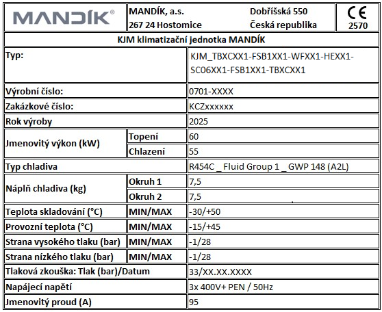 Fig. 2: Example of a PED identification plate
Each unit chamber is provided with a chamber nameplate stating the basic technical parameters, designation and function of the specific chamber. These plates facilitate quick identification during maintenance, servicing and internal record-keeping without the need to handle the documentation for the entire equipment.
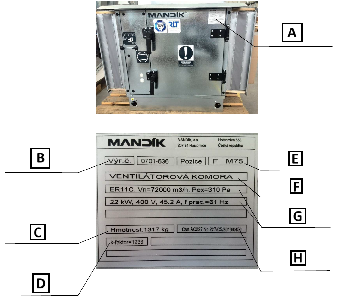 Fig.: Example of a chamber nameplate
A: Location of the nameplate on the chamber.
B: Unit serial number (complete KJM assembly).
C: Total chamber weight.
D: Additional information, e.g. the k-factor for calculating the fan airflow rate.
E: Chamber position in the unit assembly (9F0) and unit size (M75).
F: Type of component installed in the chamber.
G: Basic parameters of the component installed in the chamber.
H: Additional information, e.g. a construction product certificate.
For KJM units, each chamber is provided with an overall view of the KJM assembly highlighting the position of the respective chamber, as shown in the following figure:
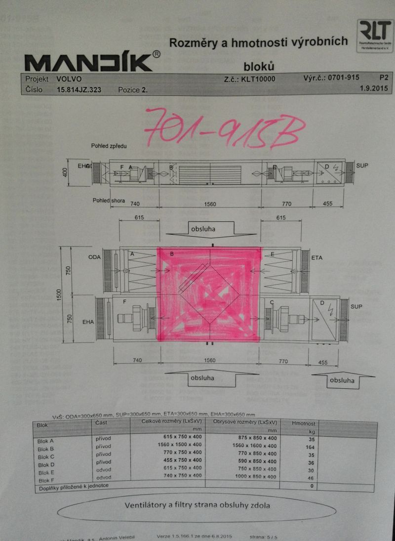 Fig.: Example of an overall view with the chamber highlighted