¶ ASSEMBLY AND INSTALLATION FOR CPV
¶ GENERAL ASSEMBLY OF THE UNIT
Before positioning the unit, the following operations must be carried out:
• Check the positioning of the unit and the stability of the supporting surface -- the unit is placed/supported over its entire footprint, the unit is positioned horizontally with the maximum permitted deviation, and damping material is inserted between the unit and the supporting surface or steel structure, as applicable
• Remove the packaging film from the unit
• Remove the inserted parts from the unit (cardboard boxes with accessories, or control assemblies and other accessories, as applicable) and store them in a safe and dry place
¶ CONNECTION OF THE UNIT TO AIR DUCTS
For rectangular outlets, the unit may be connected to the air ducts only by means of flexible connectors fitted to each inlet/outlet of the unit (they prevent transmission of vibration); for circular outlets, only by means of circular spigots with seals fitted to each inlet/outlet.
The air duct must be connected stress-free, i.e. so that its weight does not load the flexible connector and therefore the unit.
The flanged connection between the air duct and the flexible connector must always be properly sealed.
Description of the unit inlets/outlets:
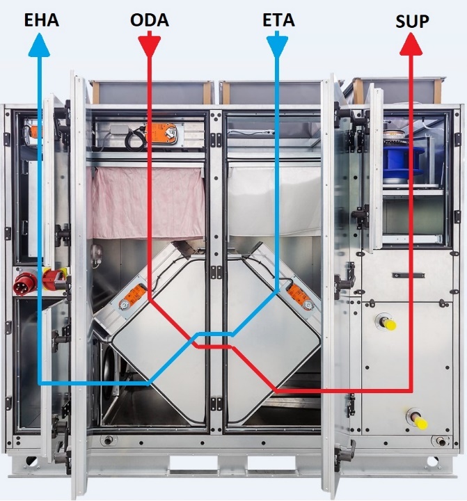
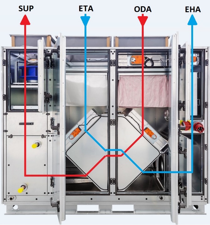
| ODA – fresh outdoor air | ETA – extract air from the room |
| SUP – supply air to the room | EHA – exhaust air to the atmosphere |
¶ CONNECTION OF THE CONDENSATE DRAIN TRAP
The condensate drain must be connected via a trap with a sufficient water column height to ensure faultless operation.
A trap connected on the negative-pressure side must always be filled with water before commissioning and after a longer shutdown so that the condensate can drain.
The pipe downstream of the trap must not be connected directly into the sewage pipe. The height of the unit above the floor/ground level must always be adapted to the required trap height.
If the trap is located outdoors, its route must be temperature-protected, e.g. with an electric heating cable.
The correct setting of the trap height according to the pressure value is as follows:
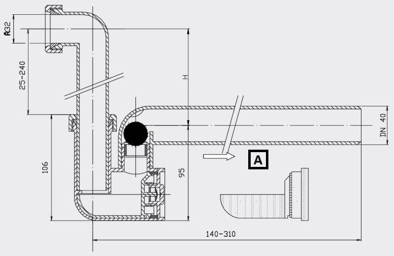
A: Cleaning insert.
Can be used for negative pressure up to 2300 Pa.
H=P/10 (P = pressure value specified in the technical specification of the unit [Pa])
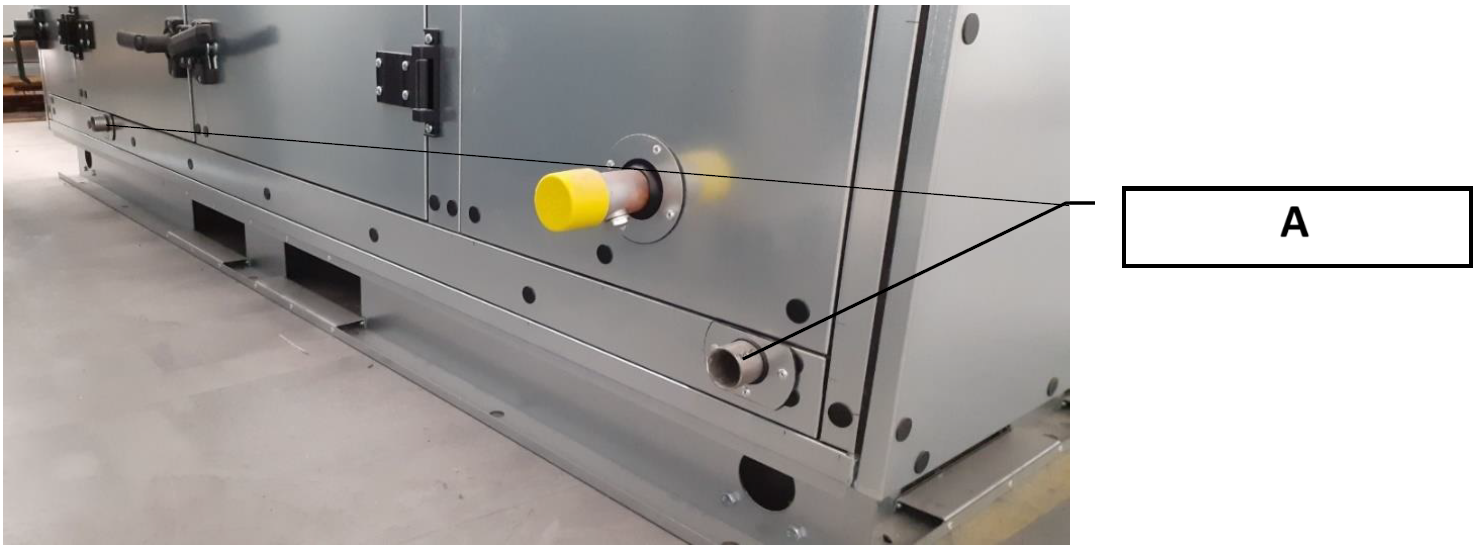
A: trap connection
¶ CONNECTION OF THE WATER HEATING/COOLING COIL
All piping must be fixed independently of the heat exchangers. Piping systems for working fluids must not act on the unit blocks or heat exchangers with their weight or expansion forces. The connections must be made so that pipe expansion due to temperature does not cause excessive loading of the spigots.
The connection must be tightened using two wrenches. Otherwise, thread deformation may occur!
The air vent valve, if not installed, must be fitted at the highest point of the hot/cold water inlet.
The heat exchanger must always be connected in counterflow!
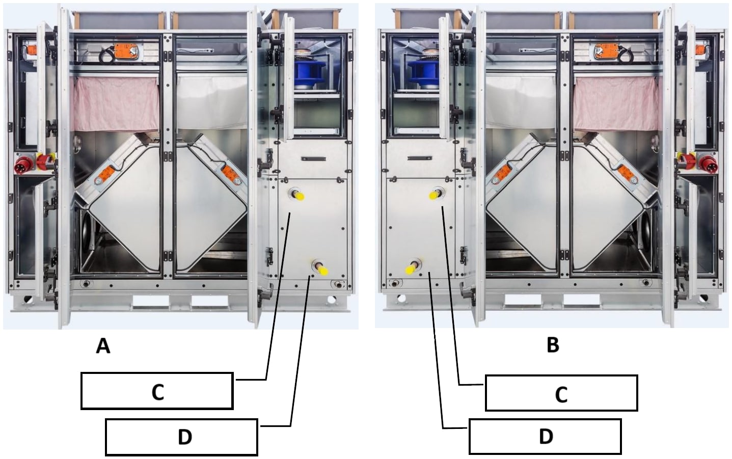
A: Fig.: Right-hand version of the unit
B: Fig.: Left-hand version of the unit
C: medium inlet
D: medium outlet
The capillary frost protection thermostat is part of the unit and is already factory-installed and connected to the measurement and regulation system.
The mixing unit for heat output control, if included in the delivery, is supplied in a cardboard box.
The installation and service manual is included in the packaging of the mixing unit. This manual contains the necessary information for safe installation, commissioning and maintenance.
Water for water heat exchangers must not contain impurities causing clogging, especially corrosion products from steel and cast-iron parts. To prevent the formation of these impurities, chemically treated water with parameters according to ČSN 07 7401 must be used.
• Hydrogen exponent pH 7 – 9.
• Water hardness 1.0 mval/l.
• Chloride content max. 30 mg/l.
• Phosphate content converted to P2O5, min. 15 mg/l.