¶ ASSEMBLY AND INSTALLATION FOR CPX
¶ UNIT SUSPENSION - GENERAL
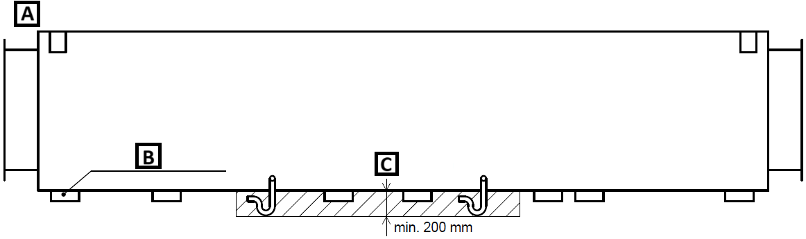
• Depending on the type and size of the unit, ensure there is free space under the unit to open the doors without obstruction – specified by the size of the particular unit doors.
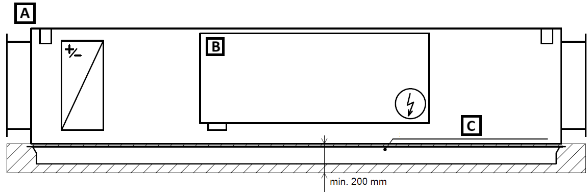
• When using the "Sliding Door Opening System" (see Additional Equipment and Configuration), a minimum free height of 200 mm is required.
• Service access to the unit across the entire footprint must be provided.
• Ensure maximum horizontal deviation of the unit does not exceed 0.5% (~ 0.3°).
• Maintain a minimum distance of 200 mm from flammable materials around the unit.
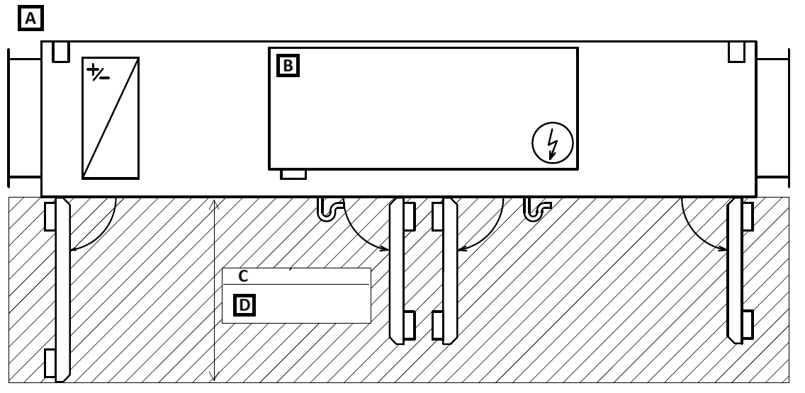
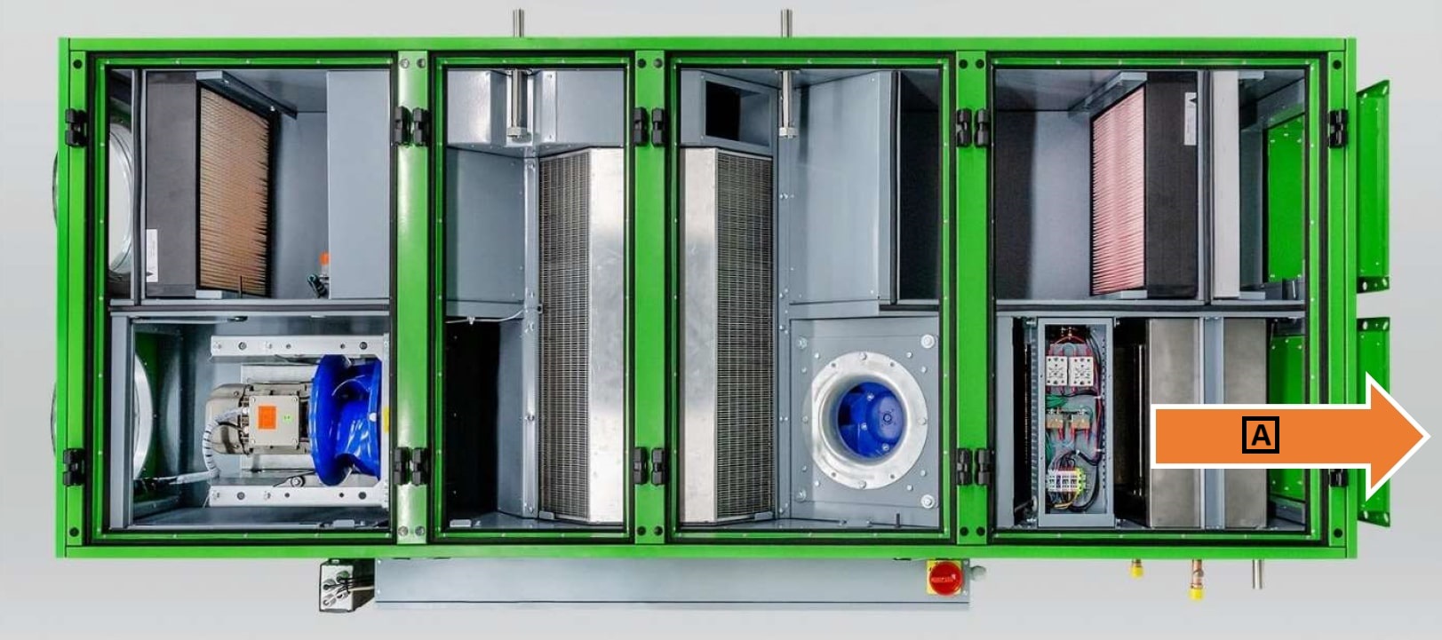
A: Front side
B: Control panel
C: Depending on the unit
D: Length of the largest doors +50 mm
¶ UNIT SUSPENSION
• Permissible handling of units for placement is detailed in section 4.
• Select suitable anchors considering the unit's weight.
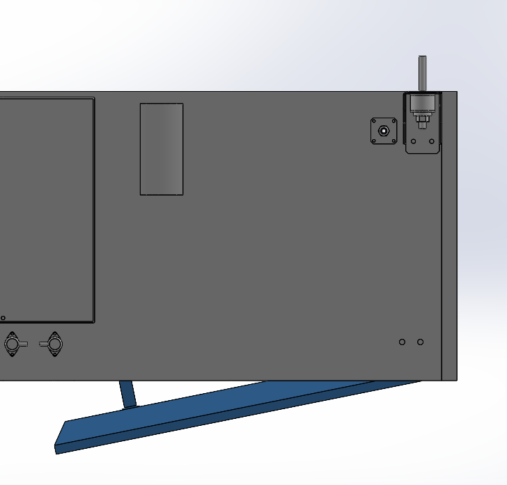
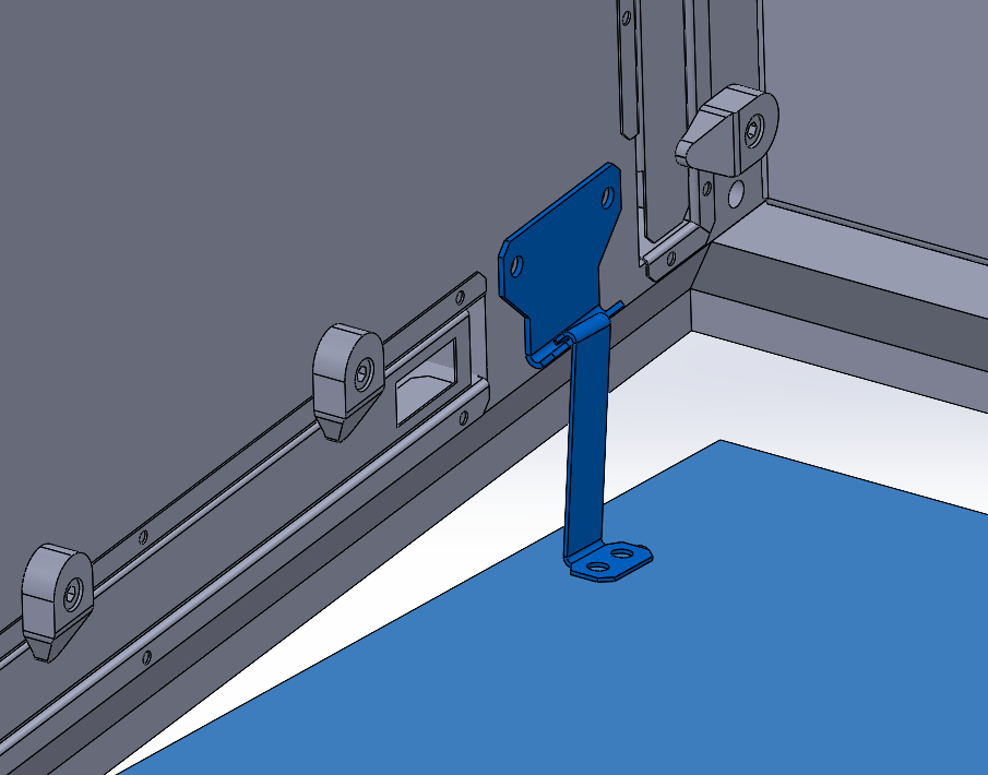
• The unit includes a total of four hangers with Silentblocks – the spacing of the hangers is shown below.
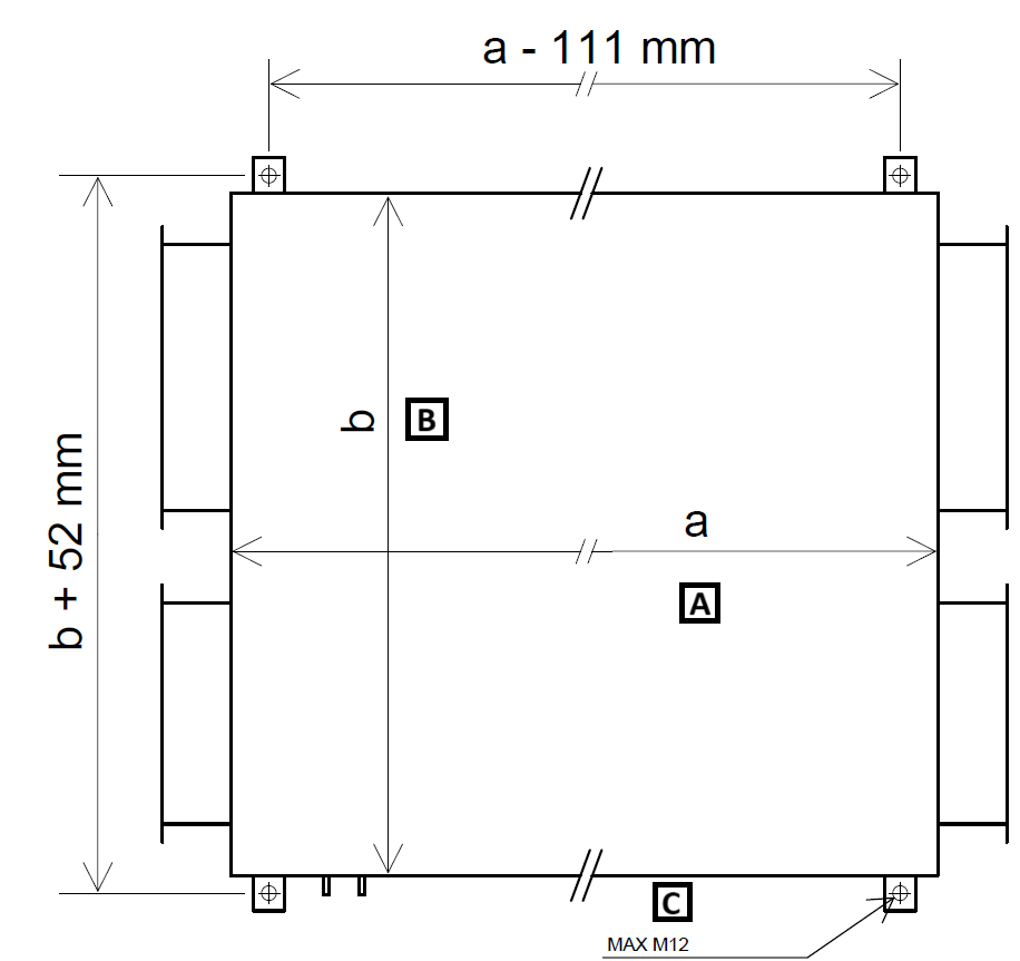
A: external unit length
B: external unit width
C: threaded rods
• Units must be suspended from securely fixed threaded rods. Shock-absorbing/silent blocks should be placed between the unit hangers and the threaded rods (see image below).
• Threaded rods and nuts are not included. It is recommended to use a washer under the nut.
A: Threaded rod (max M12, not included)
B: Unit hanger
C: Silent block (see drawing/image no. …)
D: Nut (not included)
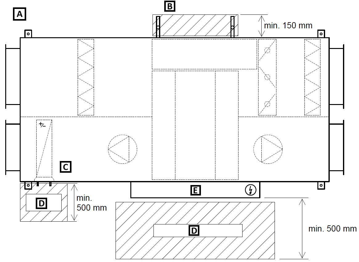
• The maximum allowable horizontal deviation is 0.5% (0.3°).
• Sufficient height under the unit must be considered (e.g., above suspended ceilings) of at least 200 mm to ensure adequate height for the siphons, which are equipped in chambers with condensate drainage, see section 0 SYPHON INSTALLATION.

• Failure to maintain the stability or horizontal alignment of the base may result in reduced unit performance or even damage, such as misalignment of fan impellers relative to the suction nozzle, incomplete chamber door closure, etc.!
• Below are the minimum required distances from the unit:
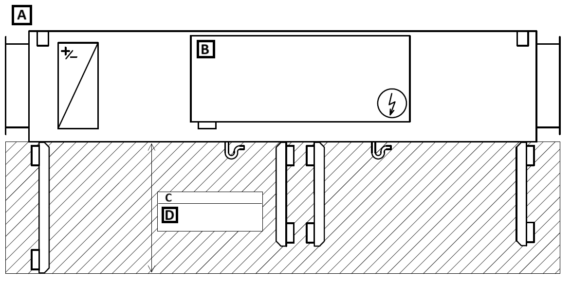
A: Front side
B: Control cabinet
C: According to the unit
D: Length of the largest door +50 mm
¶ GENERAL UNIT ASSEMBLY
Before setting up the unit, the following steps must be performed:
• Check the unit installation and stability of the threaded rods – the unit is secured at all four points.
• The unit is installed horizontally with the maximum allowable deviation (0.5% ~ 0.3°).
• Silent blocks are placed between the hanger and the threaded rod.
• Remove the protective film from the unit.
• Remove inserted parts from the unit (cardboard boxes with accessories, control nodes, and other accessories) and store them in a safe and dry place.
¶ DOOR SAFETY LOCKING
• The unit doors are equipped with a safety locking mechanism to prevent accidental opening.
• The door locks are ONLY on the indicated row of door latches (see photo below).
• It is recommended to unlock the indicated row of doors FIRST.
• After unlocking the door latches, the doors will open slightly to a secured position. By lifting the doors and pushing the locking mechanism, the doors can be fully opened.
A: Push
B: Lift
¶ CONNECTING THE UNIT TO HVAC DUCTS

Connecting the unit to HVAC ducts is possible only for rectangular outlets using damping inserts, which are installed on each inlet/outlet of the unit (to prevent vibration transmission). For circular outlets, use only circular collars with gaskets, which are installed on each inlet/outlet.
HVAC ducts must be connected without tension, meaning they should not burden the damping insert or the unit with their weight.
The flange connection between the HVAC duct and the damping insert must always be properly sealed.
Description of unit inlets/outlets:
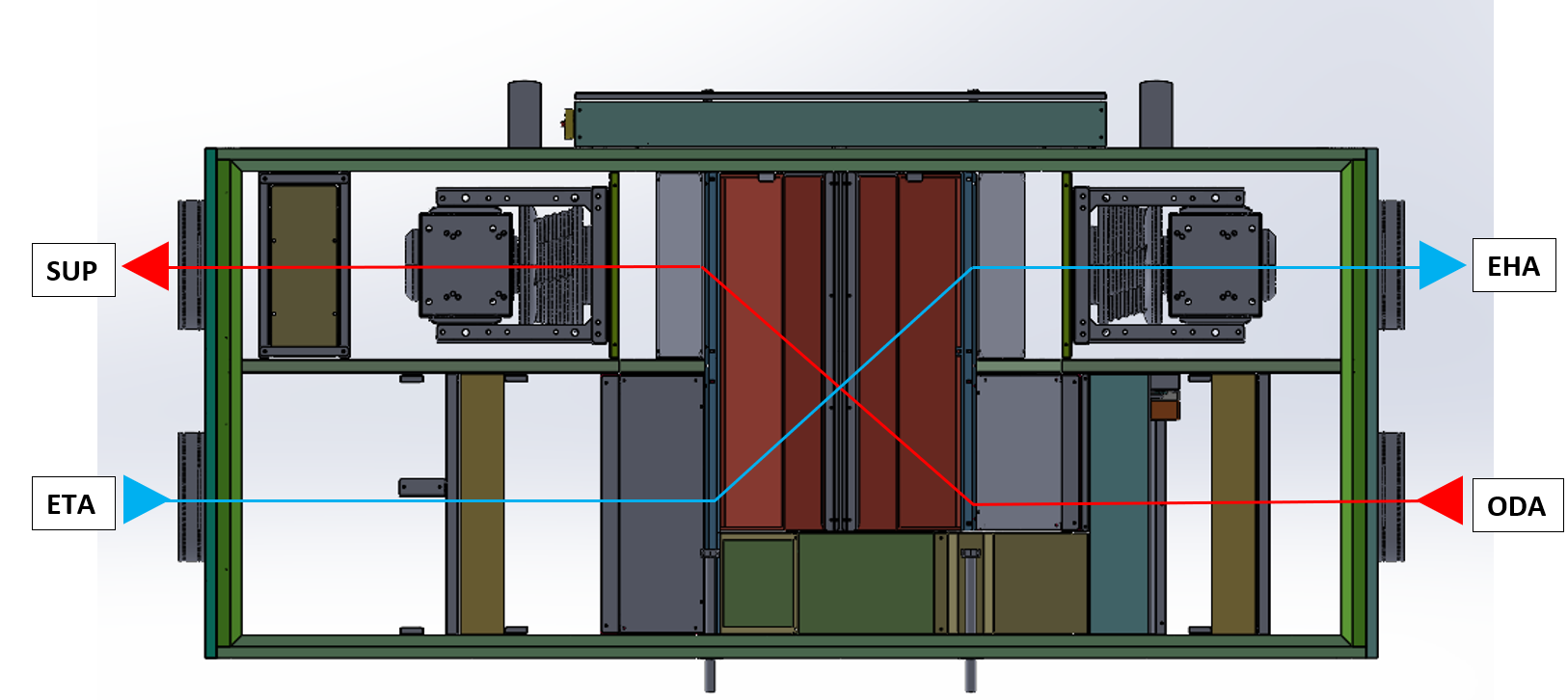
| SUP – supply to the room | ETA – extract from the room |
| EHA – exhaust air to the atmosphere | ODA – outdoor fresh air |
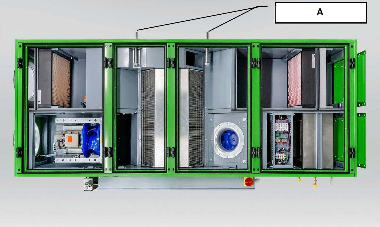
¶ CONNECTION OF THE CONDENSATE DRAIN SYPHON
The condensate drain must be connected via a siphon with sufficient water column height to ensure proper operation.
A siphon connected under negative pressure must always be filled with water before commissioning and after prolonged downtime to allow condensate to drain.
The pipe after the siphon must not discharge directly into the sewage system.
The unit height above the floor/ground level must always be adjusted according to the required siphon height.
If the siphon is placed outdoors, its route must be heated, e.g., with an electric heating cable.
The correct siphon height based on the pressure value is as follows:
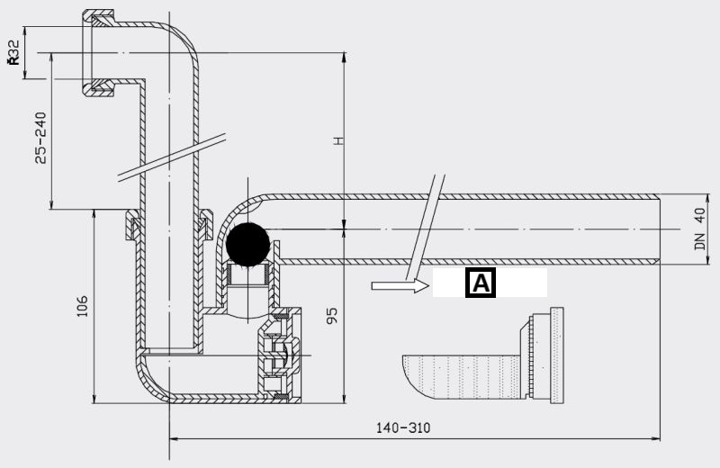
A: Cleaning insert
Can be used for negative pressure up to 2300 Pa.
H=P/10 (P = pressure value as specified in the unit's technical specifications [Pa])
A: Siphon connection
¶ CONNECTION OF WATER HEATER/COOLER
All piping must be independently fixed to avoid stressing the unit or heat exchangers with the weight and expansion forces of the piping. Connections should ensure that thermal expansion of pipes does not cause excessive load on the fittings.
Connections should be tightened using two wrenches. Otherwise, thread deformation may occur!
If not installed, the air bleed valve must be placed at the highest point of the hot/cold water supply. The heat exchanger must always be connected in counterflow!
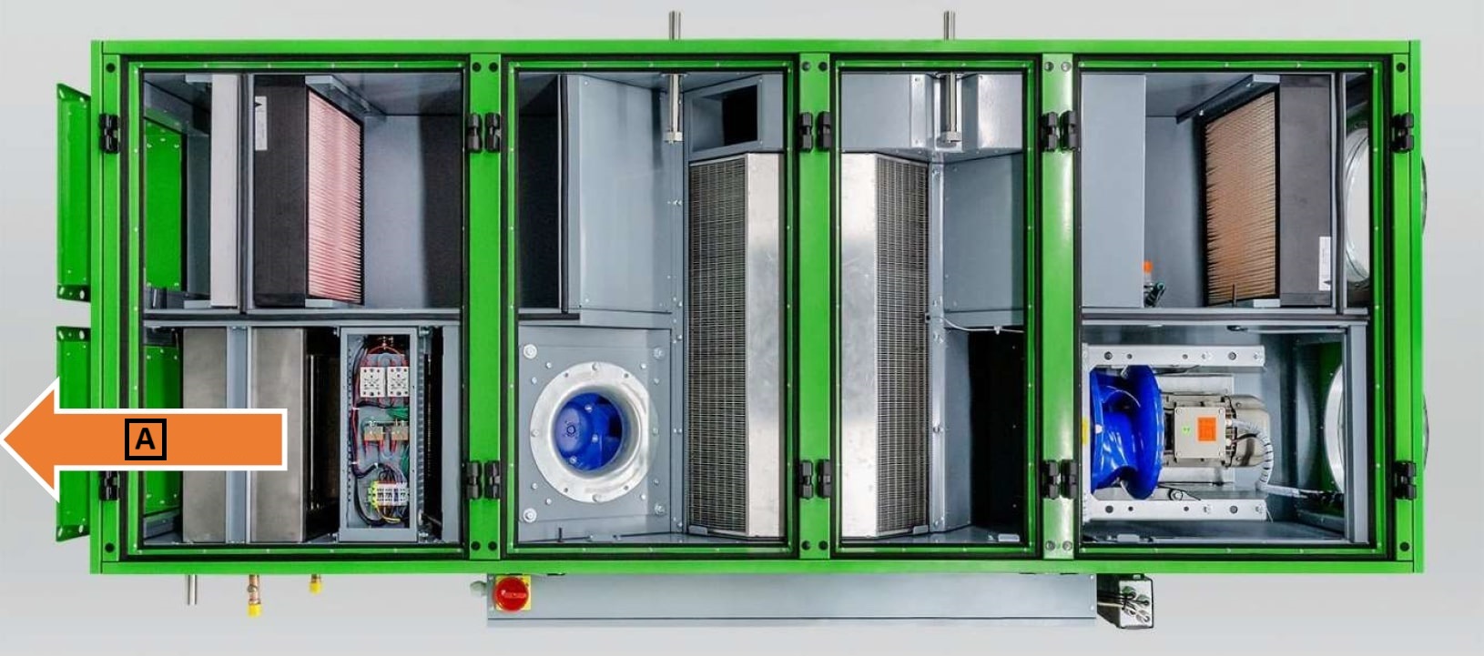
A: Air supply
A: Air supply
The capillary anti-freeze thermostat is part of the unit and is pre-installed and connected to the control system from the factory.
The mixing node for heat output regulation, if included, is provided in a cardboard box.
The installation and service manual is included with the mixing node. This manual contains the necessary information for safe installation, commissioning, and maintenance.
Water for water exchangers must be free of impurities that cause fouling, particularly corrosion products of steel and cast iron parts. Chemically treated water with parameters in compliance with ČSN 07 7401 is required to prevent such impurities.
Hydrogen exponent pH 7 − 9
• Water hardness 1.0
• Chloride content max. 30
• Phosphate content, recalculated as P2O5, min. 15 \text{mg}\ ⁄\ \text
¶ ELECTRICAL CONNECTION
Any interventions in the electrical cabinet or connection of the included components may only be performed by a qualified person according to the applicable regulations of the country in which the unit is operated!
The individual components of the unit are pre-wired at the factory to the controller terminals and tested (fans, sensors, actuators, thermostats, pressure switches, electric heater, etc.).
Only the connection of the included peripherals (remote control POL822, Touch Panel, CO2 sensor, pipe temperature sensor, control node, etc.) needs to be done. All wiring diagrams are provided in the unit's project documentation "Control and Regulation KJ MANDÍK".
The unit’s main power supply is typically ensured by the construction side. After routing the power cable through the grommet in the switchboard, it must be connected to the terminals. The main switch is located on the side of the switchboard.
For connecting the included peripherals to the terminal block, use the prepared screw terminals located above the main switch.
The main power connection for the variant with a water heater is shown in diagram D.
The main power connection for the variant with an electric heater is shown in diagram E.
Peripheral connection – CO2 sensor, remote control POL822, external air temperature sensor is shown in diagram F.