¶ ASSEMBLY AND INSTALLATION FOR CPX
¶ GENERAL UNIT SUSPENSION REQUIREMENTS
• Depending on the unit type and size, sufficient clear space must be provided beneath the unit to allow the doors to open without obstruction; the required space is determined by the size of the particular unit doors.
• When the “sliding door opening system” option is selected (see Additional Equipment and Configuration), a minimum clear height of 200 mm is required.
• For service work, access to the unit over its entire footprint must be provided.
• The maximum permitted deviation from level (0.5% ≈ 0.3°) must be observed.
• The minimum clearance between combustible objects and the unit is 200 mm.
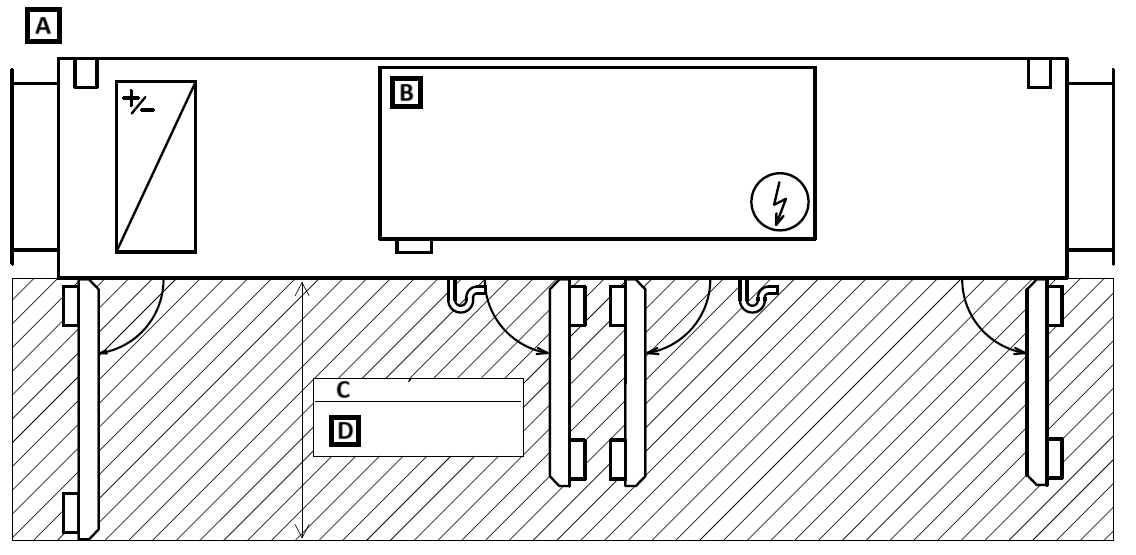
A: Front side
B: Control cabinet
C: According to the specific unit
D: Length of the largest door + 50 mm
¶ UNIT SUSPENSION
• Permitted handling of the units during positioning is specified in Section 4.
• Select suitable anchors with regard to the unit weight.
• The unit is equipped with four suspension brackets with anti-vibration mounts; the suspension bracket spacing is shown below.
Plan view:
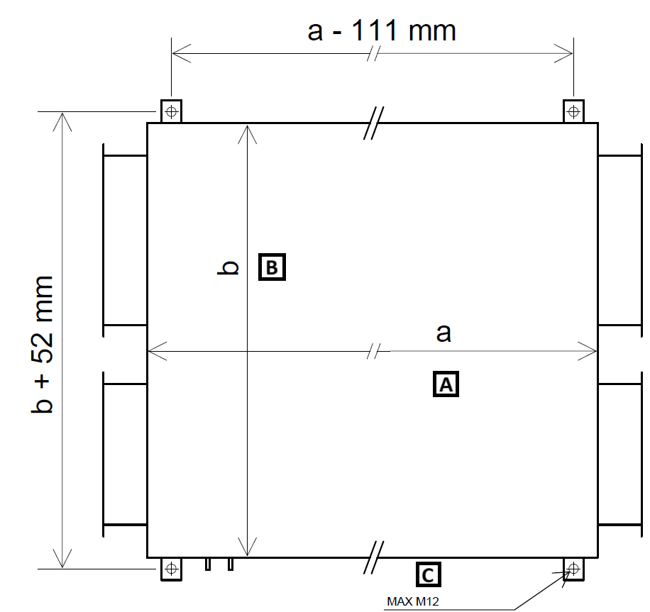
A: External unit length
B: External unit width
C: Threaded rods
• The units must be suspended from securely fixed threaded rods. Vibration-damping elements / anti-vibration mounts must be installed between the unit suspension brackets and the threaded rods (see the figure below).
• The threaded rods and nuts are not included in the scope of delivery. We recommend using a washer under each nut.
A: Threaded rod (max. M12, not included in the scope of delivery)
B: Unit suspension bracket
C: Anti-vibration mount (see drawing/fig. no. …)
D: Nut (not included in the scope of delivery)
• The maximum permitted deviation from level is 0.5% (0.3°).
• Sufficient clearance beneath the unit must be allowed for (e.g. above plasterboard suspended ceilings), with a minimum of 200 mm to provide the required siphon height for sections equipped with a condensate drain; see Section 0 INSTALLATION OF SIPHONS.
Failure to ensure a stable and level support structure may impair unit operation or even damage the unit, for example by misaligning the fan impeller relative to the inlet cone or preventing the section doors from closing properly!
The minimum required clearances from the unit are shown below:
Side view, doors open:
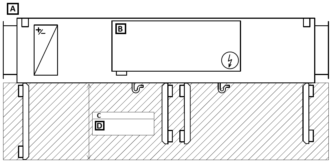
A: Front side
B: Control cabinet
C: According to the specific unit
D: Length of the largest door + 50 mm
Side view, doors closed:
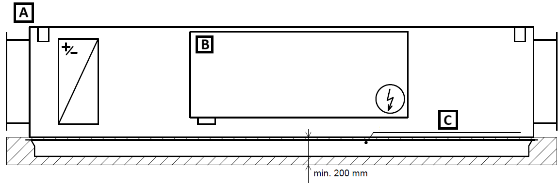
A: Front side with sliding door opening system
B: Control cabinet
C: Sliding door opening system
Rear view:
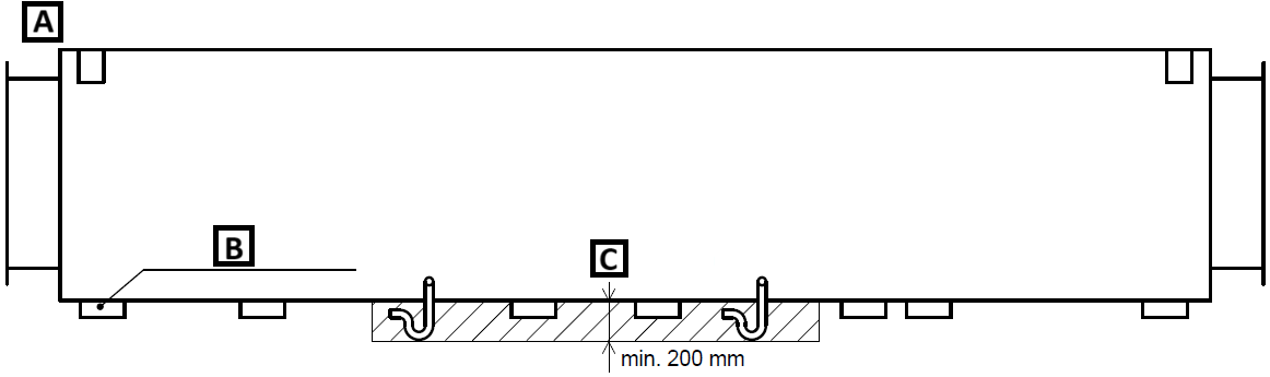
A: Rear side
B: Handle + hinge / handle-hinge
C: Condensate drain siphon
Plan view:
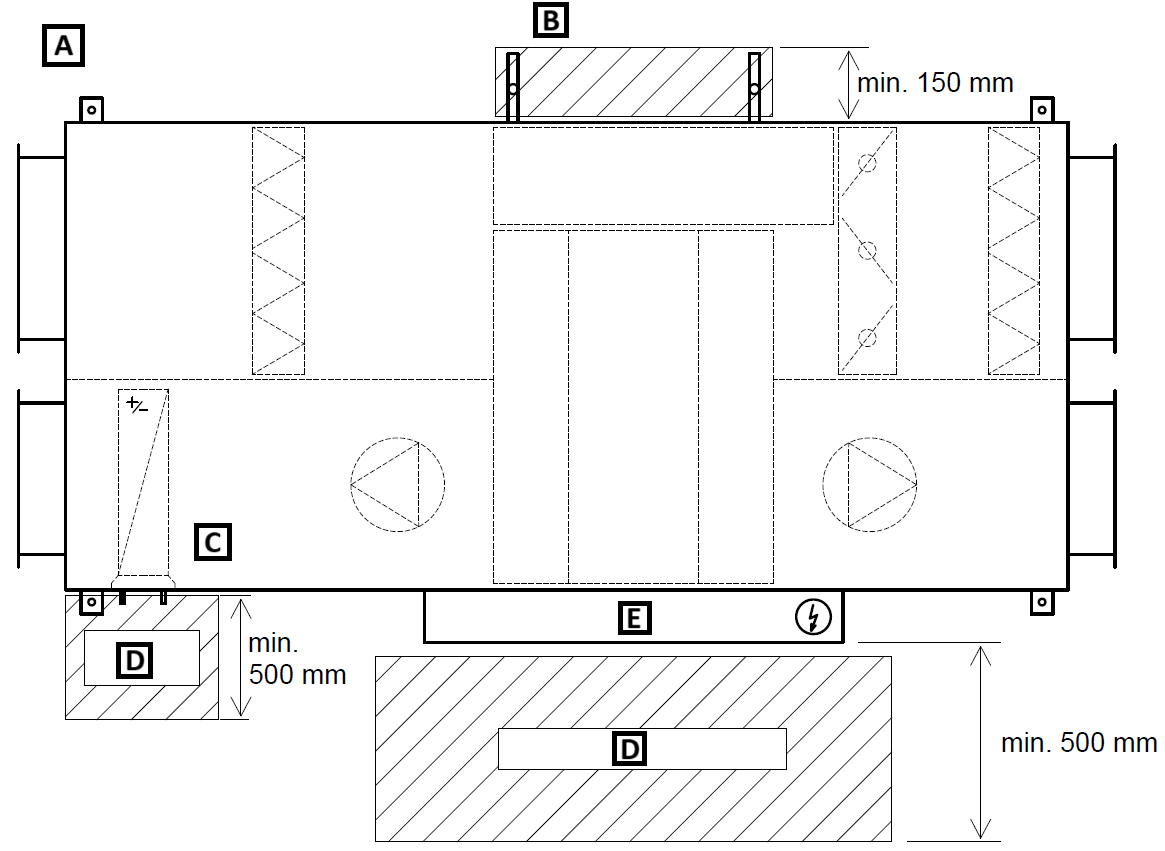
A: Plan view
B: Condensate drain siphon
C: Heating / cooling module
D: Service space
E: Control cabinet