¶ GENERAL UNIT ASSEMBLY
¶ GENERAL INSTRUCTIONS
Before assembling the unit, the following steps must be performed:
• Check the positioning of the unit and the stability of the support surface – the unit chambers are placed/supported over the entire footprint, the unit is installed horizontally within the maximum permissible deviation, and damping material is inserted between the unit and the support surface or steel structure
• Remove the packaging film from the individual chambers
• Remove the inserted parts from the unit (cardboard boxes containing connecting material, frequency inverters, control nodes, gas heater burners and other accessories) and store them in a safe, dry place
• Check the material for connecting the chambers. The types and quantities of materials are listed in the bill of materials in the accompanying documentation supplied with the unit
The material required for connecting the individual chambers is supplied in a cardboard box located in one of the chambers of the given unit. For identification, the box is also always marked with the order number (e.g. KCZ90000) and the unit serial number (e.g. 0701-100).
¶ CONNECTING MATERIAL:
• The following connecting material is supplied for assembling the unit:
 |
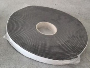 |
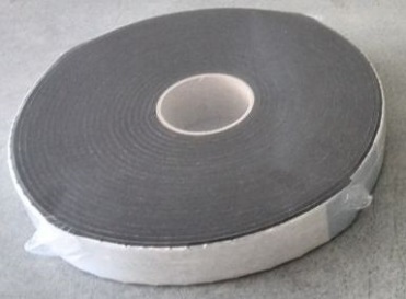
| Seal 50x5 mm intended for units with a flange thickness of 50 mm. | Seal 30x5 mm intended for units with a flange thickness of 100 mm. |
 |
 |
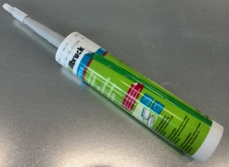 |
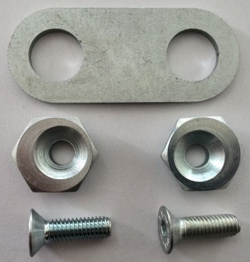
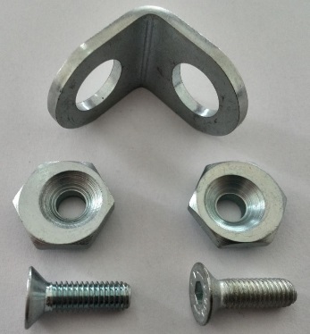
| Straight connector assembly | Right-angle connector assembly | PU sealant for mounting roof covers |
Right-angle connectors and PU sealant for roof covers are supplied only depending on the configuration.
¶ CONNECTION OF VERTICAL/HORIZONTAL AND CEILING-SUSPENDED UNIT
Procedure for connecting the unit chambers:
• Bond the seal to the chamber flanges – always to one flange of the two adjacent chambers; see the following figure.
A: Chamber flange without seal.
B: Opposite chamber flange with seal.
¶ TYPES OF FLANGES:
There are two types of flanges, or two procedures for installing the seal according to the following figures:
¶ 1) Flange with a thickness of 50 mm
For smaller units
Flange:
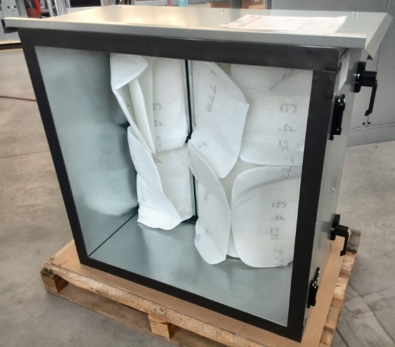
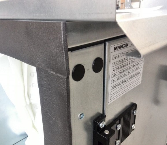
Use seal 50x5 from the supplied connecting material.
For indoor unit placement, polyurethane ST seal is supplied; for outdoor placement, EPDM seal is supplied.
Apply the seal in one row around the circumference of the flange. Adjacent seal sections must fit against each other and must not create a gap that would cause leakage; see the figure above.
¶ 2) Flange with a thickness of 100 mm
For larger units or units with T1 TB1 casing
Flange:
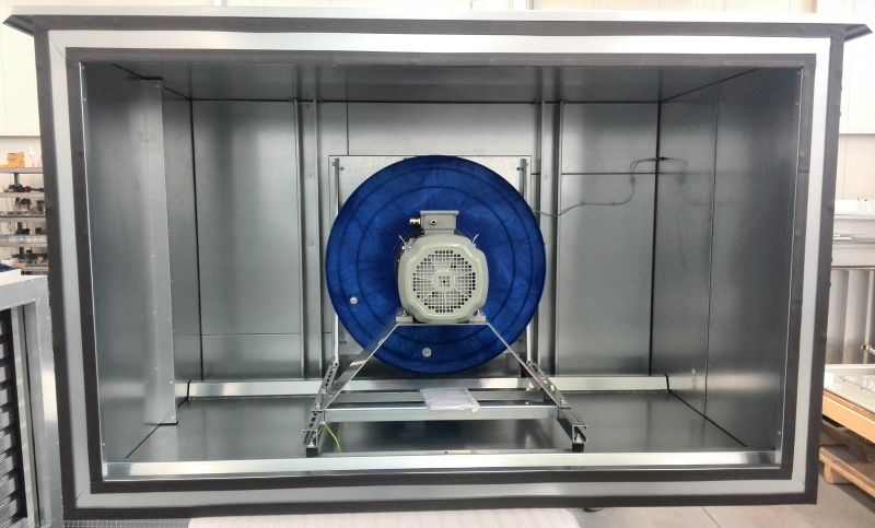
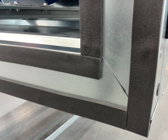
Use seal 30x5 from the supplied connecting material.
For indoor unit placement, polyurethane ST seal is supplied; for outdoor placement, EPDM seal is supplied.
Apply the seal in two rows around the circumference of the flange according to the figure. One row of seal must be bonded to the outside of the flange and the other row of seal must be bonded to the inside of the flange. Adjacent seal sections must fit against each other and must not create a gap that would cause leakage.
¶ TYPES OF ECCENTRICS:
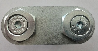
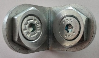
Connecting eccentrics are used to connect chambers of vertical type units (chambers above each other) or horizontal type units (chambers side by side). The types of eccentrics, their function and assemblies are shown in the following figures.
¶ 1) Straight connecting eccentric
For chambers aligned in outline
A: Eccentric plate
B: Eccentric nut
C: Eccentric bolt
 |
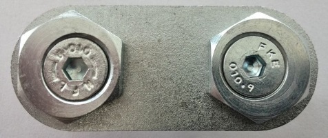 |
| “Released” position. | “Tightened” position. |
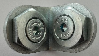
¶ 2) Right-angle eccentric
For chambers with different outlines, e.g. rotary heat recovery exchanger chamber or gas heater chamber
A: Eccentric plate
B: Eccentric nut
C: Eccentric bolt
 |
 |
| “Released” position. | “Tightened” position. |
¶ CONNECTION OF CHAMBERS USING CONNECTING ECCENTRICS:
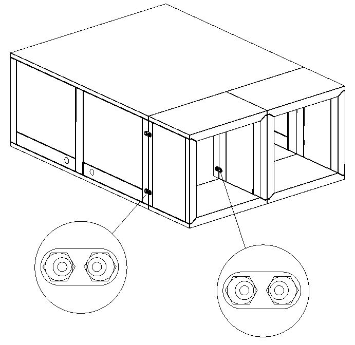
The press nuts of the connection between adjacent chambers may be located on the outside of the chamber casing or on the inside. It always depends on the unit configuration. The procedure for installing the connecting eccentrics is the same for both types of location.
For the final arrangement of the connecting eccentric, see the following figure. For proper function of the eccentrics and the seal between the chamber flanges, it is important to tighten the bolts into the “tightened” position; see the following figure.
A: Pulling the chambers together without a gap
B: “Tightened” position of the eccentric
Eccentrics for connecting chambers are not intended to move the chambers into the assembly position for final tightening of the eccentric!!! A suitable tool must be used, e.g. a lever clamp, with which the chambers can be pulled together through the side circular openings of the base frame, or tightening straps can be used to pull adjacent chambers together over the flanges.
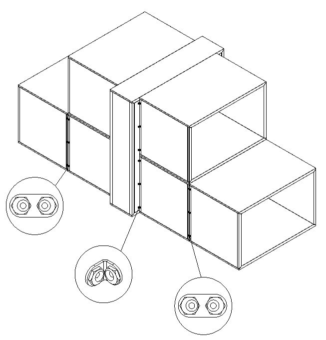
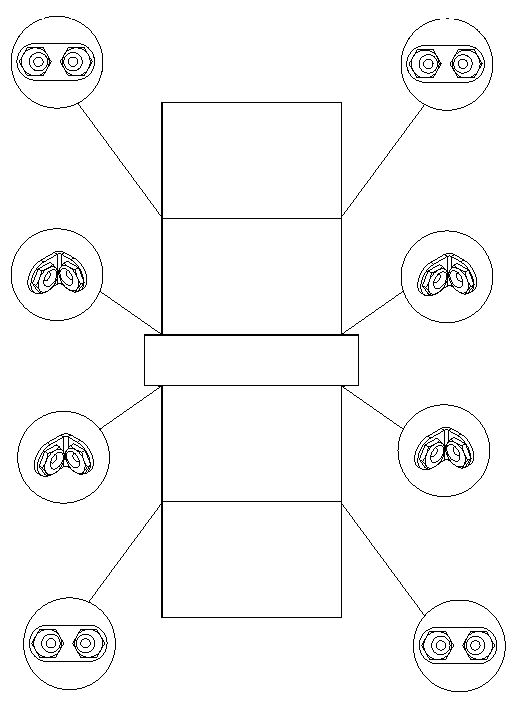
Depending on the unit configuration, one unit may contain:
• both types of connecting eccentrics – straight and right-angle
• both types of press nut placement – external and internal.
The following figure shows an overview of possible unit configurations:
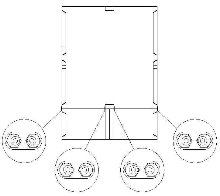
This type of unit and method of connecting the chambers is identical to the version of the assembled unit installed under the ceiling (“ceiling-suspended”).
¶ CONNECTION OF A UNIT INTENDED FOR OUTDOOR USE
The required chambers of the unit intended for outdoor use are fitted with roof covers. The roof covers are already installed on the respective chambers at the factory. The correct procedure for connecting the roof covers is shown in the following figure.
The sides of the roof covers of the chambers on the side of the mutual connection with the adjacent chamber are always finished with two types of joints, “Z” and “U”; see the following figure.
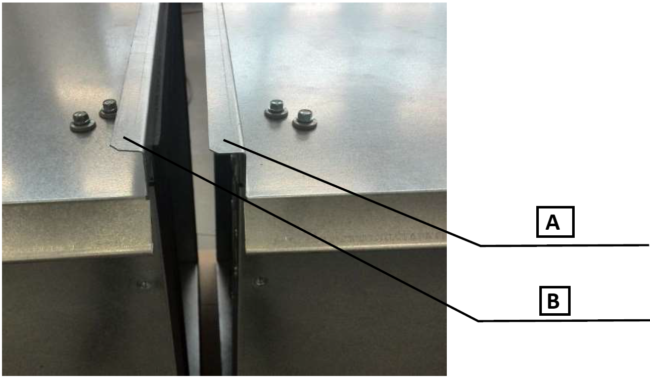
A: “Z” end
B: “U” end
Before connecting the chambers to each other, the roof-cover joints must be sealed with PU sealant from the installation kit. Correct assembly of the chamber and roof cover is shown in the following figure:
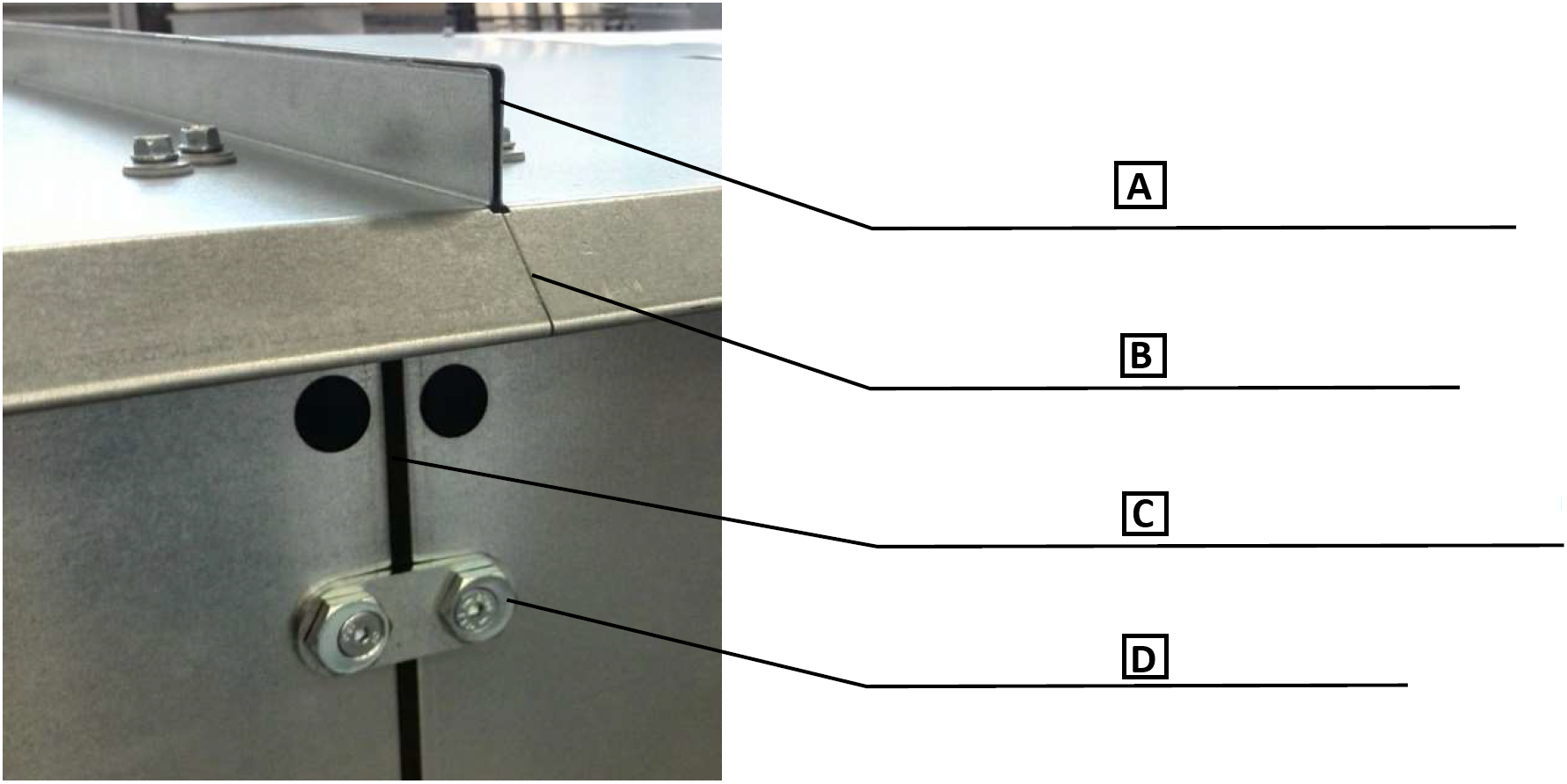
A: Seal the roof-cover connection with PU sealant
B: Correct seating of the roof covers
C: Seal 50x5 mm, or 30x5 mm
D: Eccentrics in the “tightened” position
If the roof covers are packed on a pallet, they must be installed and fastened to the individual chambers. For each chamber, the roof parts are packed separately, including a drawing for correct installation of the individual roof parts on the given chamber. Each roof part is provided with a label with the part name according to the drawing. See the following figure.
A: Orient the parts so that drip edges are located on the front/rear/side free side of the chamber.
B: The roof part name on the drawing matches the label on the part.
C: Individual roof parts of the chamber.
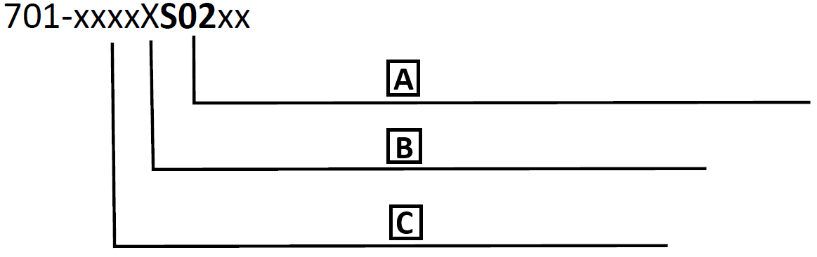
PART NAME ON THE LABEL:
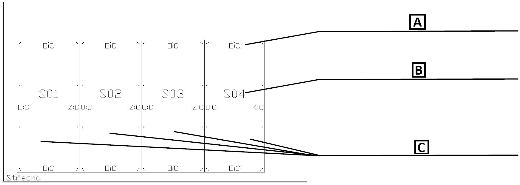
A: S02 (example) – roof part number matching the drawing
B: X – chamber letter in the AHU assembly
C: xxxx – serial number of the AHU
(The roof drawing is located in the lower left corner of the drawing.)
For fastening the individual roof parts, use self-tapping screws with rubber washers in the pre-prepared holes in the roof parts and chamber. The screws are included in the installation kit.
For proper function of the roofs, it is very important to seal the parts to each other and between the chambers thoroughly, including the corners!!! See the following figure.
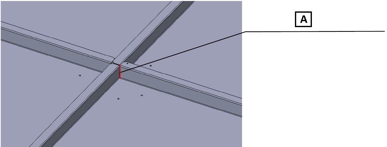
A: Thorough sealing of all roof corners!!!
FURTHER DESCRIPTION OF THE PROCEDURES FOR ASSEMBLING INDIVIDUAL BUILT-IN COMPONENTS/CHAMBERS IS PROVIDED IN SEPARATE CHAPTERS ACCORDING TO THE SPECIFIC BUILT-IN COMPONENT.