¶ PLATE HEAT RECOVERY EXCHANGER CHAMBER
¶ IDENTIFICATION, ASSEMBLY AND INSTALLATION
The chamber contains an air-to-air plate exchanger with a thermal by-pass.
The chamber is normally factory-fitted with the plate exchanger, by-pass damper and, where applicable, droplet eliminator.
The chamber may, if required, contain a mixing damper. The damper is normally factory-fitted.
The chamber is normally factory-fitted with trays for condensate drainage from the surface of the plate exchanger. The outlets are fitted with DN32 stainless-steel pipes for siphon connection.
Installation of the siphon on the positive-pressure or negative-pressure side is described in the chapter Accessory installation.
The actuator of the by-pass damper, if included in the delivery, may be factory-fitted on request. Otherwise, the recommended installation is described in the chapter Accessory installation. The electrical wiring of the actuators is described in the document “Manual for Installation and Operation of the Measurement and Regulation System”.
The layout position of the dampers (top left/top right/bottom left/bottom right), or of their actuators, can be found in the unit technical data sheet in the overall assembly drawing or according to the stickers on the service side of the chamber.
Access to the actuators is shown in the following figure.
- Vertical design (supply and extract branches above each other)
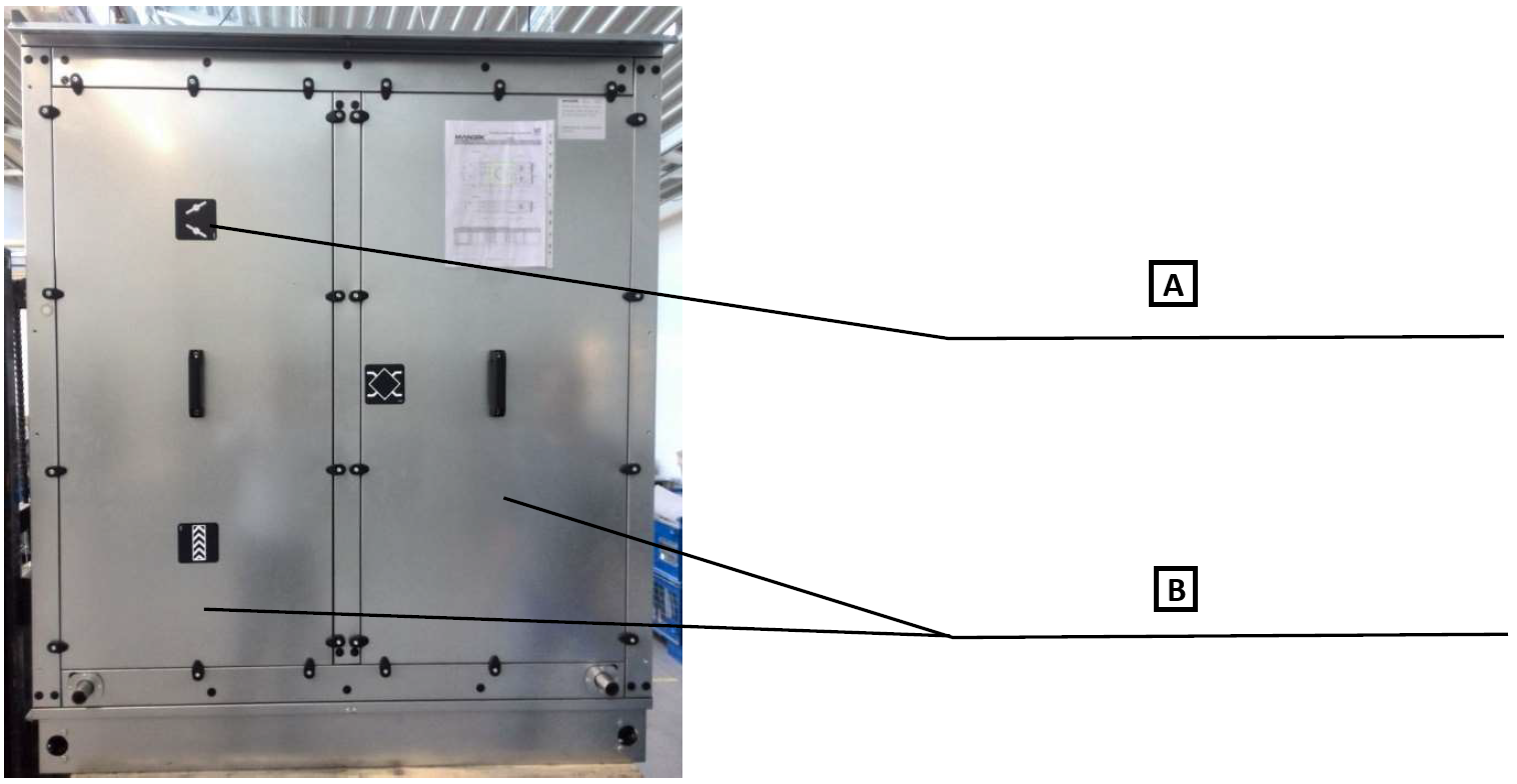
A: Sticker indicating the layout position of the damper in the chamber.
B: Chamber service panels. The panels can be removed using a 5.0 mm Allen key.
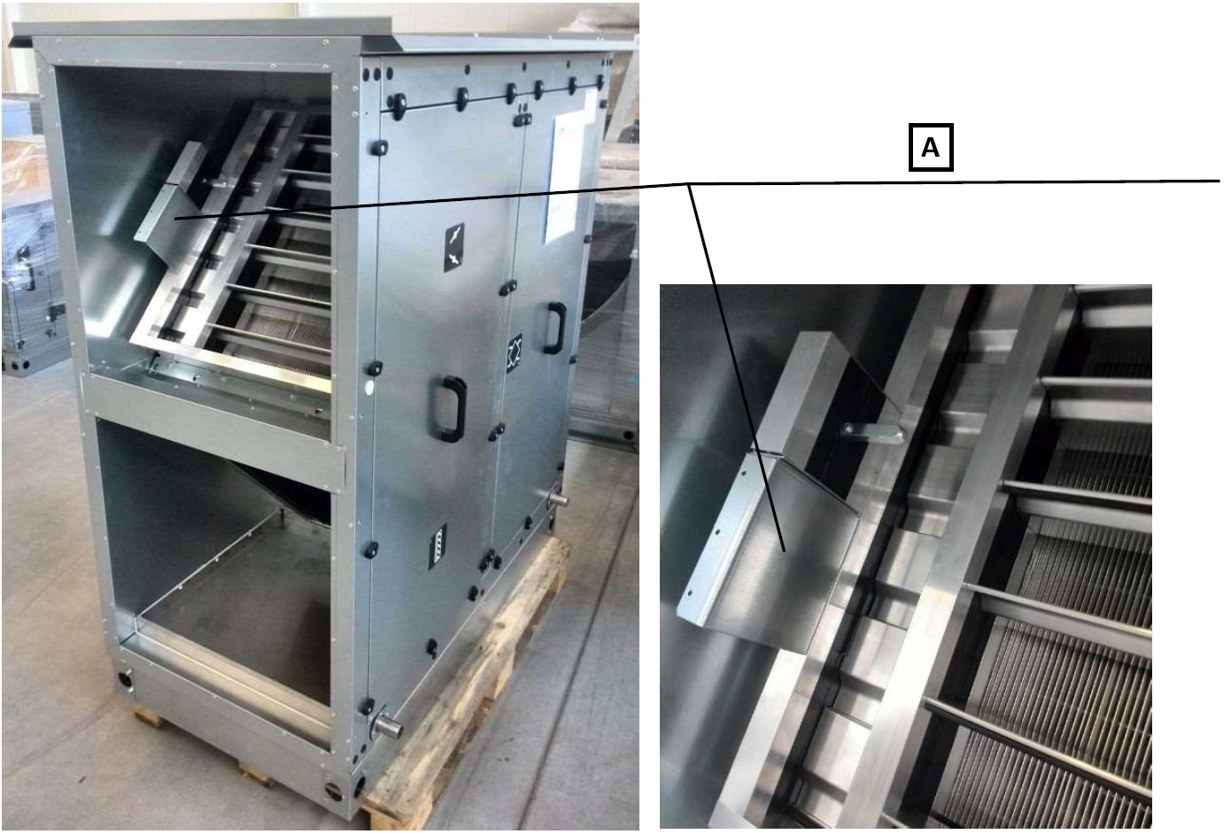
A: The actuator is always located inside the chamber by the rear wall, where a bracket is prepared for fastening it.
- Horizontal design (supply and extract branches next to each other)
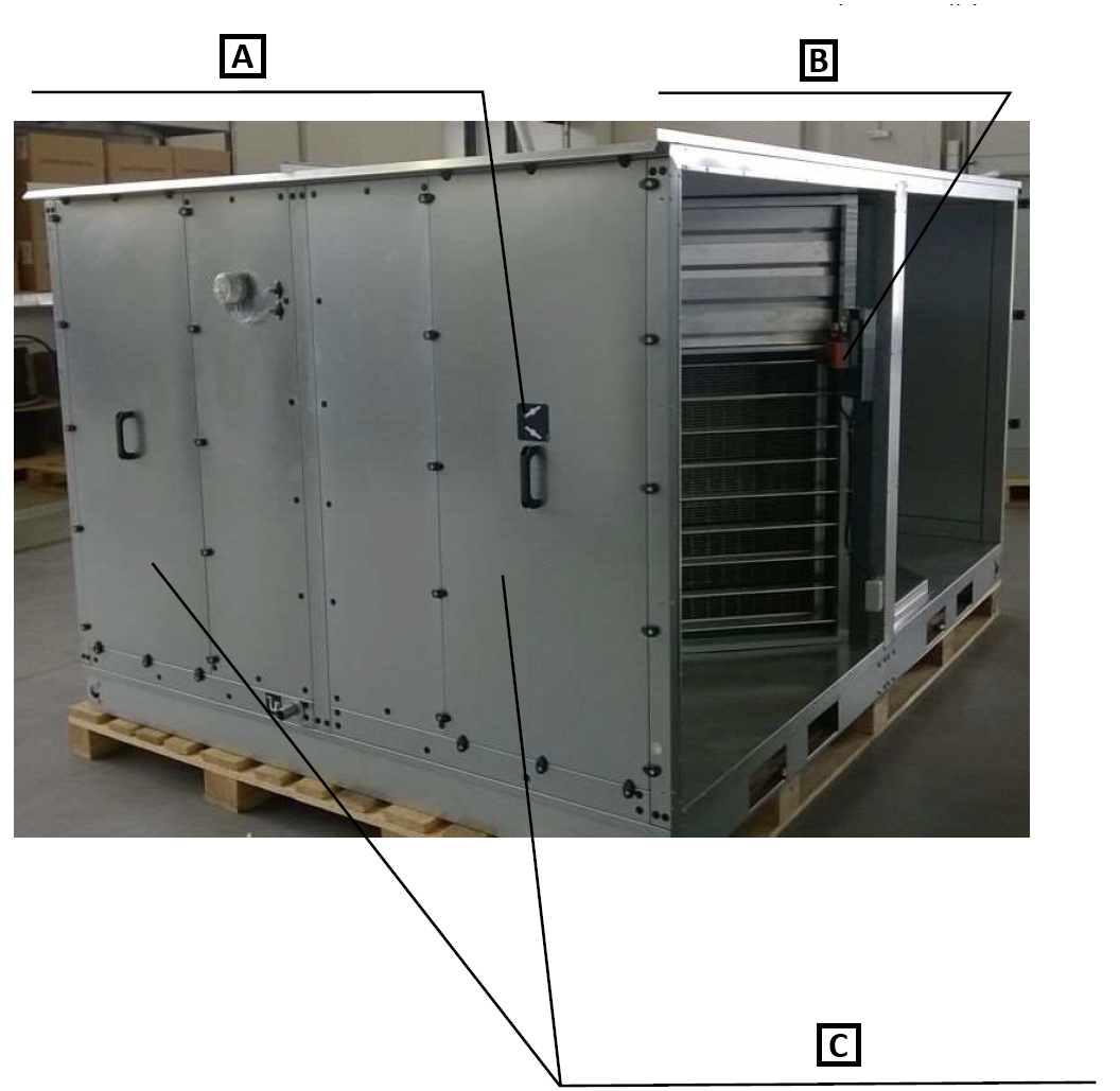
A: Sticker indicating the layout position of the damper in the chamber.
B: The actuator is always located inside the chamber.
C: Chamber service panels (front and rear wall of the chamber). The panels can be removed using a 5.0 mm Allen key.
¶ SPLIT PLATE HEAT RECOVERY EXCHANGER CHAMBER
Units of type M20 or P20 and larger can be designed and supplied in a split version. A detailed description of the assembly is provided in the annex.
¶ COMMISSIONING
¶ TASKS BEFORE COMMISSIONING
| __________________ | __________________ | ||
|---|---|---|---|
| Order number: | User: | ||
| Date: | Commissioning technician: | ||
| Project name: | |||
| Serial number: | |||
| Address: | |||
| Date of first start-up: | Position: |
Tasks for the plate heat recovery chamber
| No. | Description of service task | Task carried out | Measured or set value | Note | |
|---|---|---|---|---|---|
| YES | NO | ||||
| 1.01 | Check the cleanliness and absence of damage to the heat-transfer surface of the exchanger. | ||||
| 1.02 | Check the free movement of the by-pass damper, or of the mixing damper where applicable. | ||||
| 1.03 | Check the intact condition of the droplet eliminator, if included. | ||||
| 1.04 | Check the installation of siphons according to the assembly instructions. | ||||
| 1.05 | |||||
| 1.06 | |||||
| 1.07 |
Tasks for the heat recovery chamber - measurement and regulation system
| No. | Description of service task | Task carried out | Measured or set value | Note | |
|---|---|---|---|---|---|
| YES | NO | ||||
| 1.08 | Check the installation and wiring of the plate heat recovery damper actuator (by-pass/mixing) according to the assembly instructions. | ||||
| 1.09 | Check the installation of the differential pressure switch/digital manometer according to the assembly instructions - plate heat recovery. | ||||
| 1.10 | Check the electrical wiring and setting of the differential pressure switch/digital manometer according to the assembly instructions - in particular the setting of the final pressure loss (plate heat recovery). |
Special tasks:
| No. | Description of service task | Task carried out | Measured or set value | Note | |
|---|---|---|---|---|---|
| YES | NO | ||||
| 1.16 | |||||
| 1.17 | |||||
| 1.18 | |||||
| 1.19 |
| In....................on.................... | |||
| ______________________ | ______________________ | ||
| Stamp and signature of the service technician: | Stamp and signature of the authorised representative of the equipment operator | ||
| ______________________ | ______________________ | ||
| Surname and number of the service technician in block capitals | Surname of the authorised representative of the operator in block capitals. |
*Enter the value only where a quantity has to be measured.
¶ TASKS DURING COMMISSIONING
¶ TASKS DURING FIRST START-UP
During first start-up, check in particular:
Plate heat recovery exchanger:
• Correct function of the condensate drain siphon (height, priming with water)
• Correct direction of rotation of the by-pass/mixing damper, or switching of the actuator switch, see Section 5.28 ACTUATOR INSTALLATION
¶ OPERATION AND MAINTENANCE
Detailed operation instructions and maintenance and service procedures are provided in the following paragraphs and also in the individual parts of the unit.
The blades of the open damper must be secured against spontaneous or accidental closing. Never put limbs between the blades of an open damper; there is a risk of serious injury!
Check the condition and contamination of the heat recovery exchanger, the function of the dampers, condensate drains and droplet eliminator.
Remove contamination from the heat recovery exchanger by blowing it through with air, steam or a hot-water pressure washer. In all cases, care must be taken to prevent deformation of the exchanger plates.
Check the dampers for contamination, possible damage and blade mobility. Remove any dust deposits with a vacuum cleaner. The surface of the damper blades can then also be cleaned with a damp cloth. The plastic gear wheels of the dampers are made of a material that does not require additional lubrication. For dampers with linkage, lubricate the necessary points of the lever mechanism with lubricating spray.
Check the condition and function of the condensate drain trays, the unobstructed flow from the tray and the condition and function of the siphon; clean and top up with water as required. Before winter, check the functionality of anti-freeze measures at the condensate drains (if there is a risk of freezing).
Also check for deposits and check the condition and cleanliness of the droplet eliminator; remove it and clean it if necessary.
¶ SERVICE AND MAINTENANCE TASK INTERVALS
| SERVICE AND MAINTENANCE TASKS | ||||||||
|---|---|---|---|---|---|---|---|---|
| Inspection task | Unit in operation Y/N* | Service/remedy method | Intervals (months) | |||||
| PLATE HEAT RECOVERY EXCHANGER | 1 | 3 | 6 | 12 | ||||
| 01. | Check that the heat-transfer surface of the exchanger is not damaged. | N | repair/replacement | ✓ | ||||
| 02. | Check the cleanliness of the heat-transfer surface of the exchanger. | N | cleaning | ✓ | ||||
| 03. | Check the free movement of the by-pass/mixing damper. | N | repair/cleaning | ✓ | ||||
| 04. | Check the dampers for contamination. | N | cleaning | ✓ | ||||
| 05. | Check the condition and cleanliness of the condensate droplet eliminator. | N | cleaning/repair | ✓ | ||||
| 06. | Check the cleanliness and unobstructed flow of the condensate drain. | N | cleaning/repair | ✓ | ||||
| 07. | Check the condition and water priming of the condensate drain siphon. | N | repair | ✓ |
* operating status of the unit when the inspection is performed