¶ HANDLING, TRANSPORT AND STORAGE
¶ Transport and storage instructions
• Units are delivered as individual chambers or compact blocks. The roof for outdoor units is delivered either mounted on the unit or dismantled on a separate pallet. This depends on the unit size and the method of transport.
• Units are delivered wrapped in plastic film; larger chambers and units intended for export are placed and packed on pallets. The packaging method can be agreed individually.
ATTENTION: plastic film is transport packaging intended to protect the chambers during transport and must not be used for long-term storage of the chambers. Temperature changes during transport may cause water vapour to condense inside the packaging, thereby creating conditions inside the packaging that are suitable for corrosion of the materials used on the chambers (e.g. white corrosion of galvanized components). Therefore, after transport is completed, this transport packaging must be removed without delay and air must be allowed to reach the chambers so that the chamber surfaces can dry.
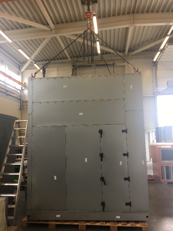
• During transport and relocation, individual chambers may only be transported using forklift trucks, transport slings or crane chains, and the relevant safety regulations must be observed (ČSN ISO 8792). Chambers without lifting lugs may only be lifted from below; chambers with lifting lugs may also be lifted using the prepared lugs on the chamber roof. When lifting by crane, either slings passed underneath the unit may be used, in which case, for larger pieces, the slings must be spread at the top or the places where the sling could cause deformation of the chamber must be additionally reinforced, or the prepared lifting lugs in the upper corners of the chambers may be used, in which case, for larger pieces, the chains must be spread at the top so that tensile forces acting at an angle cannot cause deformation of the chamber. When transporting by forklift truck, the chamber must be supported across its entire width to prevent damage to the chamber bottom.
Permitted handling methods are shown in the following figures.
• Upon receipt, it is necessary to check whether the product has been delivered in the agreed design and scope and whether it has not been damaged during transport. In case of damage during transport, the receiving party must record the extent of the damage on the carrier’s delivery note. Failure to follow this procedure may result in the rejection of a claim for damage caused during transport.
• Units and other delivered accessories must be stored in dry, dust-free areas protected from rain and snow, where the ambient temperature does not fall below +5 °C, and they must be protected against mechanical damage, contamination and corrosion caused by permanent condensation of water vapour on the surface of the unit.
ATTENTION: If the equipment is suspended during transport, keep a safe distance from the load and never stand under the load. Keep the lifting acceleration and speed within safe limits. Never leave the equipment suspended longer than absolutely necessary!
¶ Permitted handling methods:
¶ 1. Transport and handling using a pallet truck
The chamber base frame has openings intended for this purpose. When used, the forks of the pallet truck must always be positioned under the entire chamber, see figures.
¶ 2. Transport and handling using a forklift truck
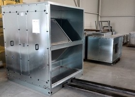
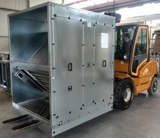
The chamber base frame has openings intended for this purpose. When used, the forks of the forklift truck must always be positioned under the entire chamber, see figures.
ATTENTION: The chamber is not always balanced by weight. Handling and lifting height must be adapted accordingly!
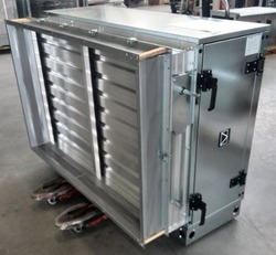
¶ 3. Transport and handling of the chamber on a non-returnable pallet
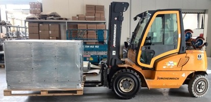
When used, the forks of the forklift truck or the pallet truck must always be positioned under the entire pallet.
ATTENTION: The chamber is not always balanced by weight. Handling and lifting height must be adapted accordingly!
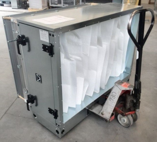
¶ 4. Handling a chamber without a base frame using slings
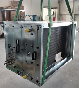
Chambers without a base frame are delivered on non-returnable pallets.
The slings must always be passed under the entire length of the chamber or, as applicable, under the entire width of the chamber (in the direction of airflow).
The slings must always be positioned at the edges of the chamber to ensure weight balance.
The chamber may only be transported in its horizontal working position.
To prevent deformation of the chamber at points exposed to sling pressure, the sling clamping angle of 50° must be observed, see the figure below, and the contact points must be fitted with sufficiently rigid elements, see the figure above.
If the chamber is equipped with a roof, the slings above the chamber must always be sufficiently spread so that the slings do not deform the roof and the chamber frame.
ATTENTION: Only suitable and approved lifting accessories may be used for handling and transporting chambers!
During handling, observe all applicable technical and legal regulations of the relevant country, e.g. ČSN EN 13 155+A2, ČSN ISO 12480-1.
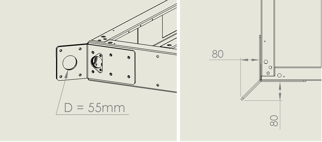
¶ 5. Handling a chamber with a base frame using steel pipes and slings
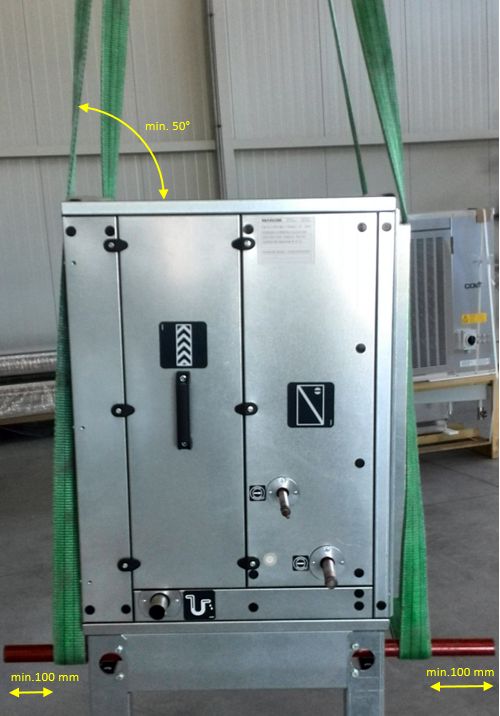
The pipes must be passed through the circular openings in the corner of the base frame along the entire length of the chamber or, as applicable, along the chamber width. The minimum pipe overlap relative to the sling is 100 mm. It is advisable to fit the pipe ends with clamps to prevent the slings from slipping off. Pipe diameter 40–45 mm. Pipe wall thickness at least 5 mm. The minimum sling clamping angle relative to the upper edge of the chamber is 50°. See the figure above.
The chamber may only be transported in its horizontal working position.
To prevent deformation of the chamber at points exposed to sling pressure, the contact points must be fitted with sufficiently rigid elements, see the figure above.
If the chamber is equipped with a roof, the slings above the chamber must always be sufficiently spread so that the slings do not deform the roof and the chamber frame.
If the base frame is fitted with feet, as shown in the figure above, the procedure for inserting the pipe and tying the slings is the same as for a base frame without feet.
ATTENTION: Only suitable and approved lifting accessories may be used for handling and transporting chambers!
During handling, observe all applicable technical and legal regulations of the relevant country, e.g. ČSN EN 13 155+A2, ČSN ISO 12480-1.
¶ 6. Handling a chamber using a crane/helicopter when suspended from separate lifting lugs – type 1 “light-duty”
Limits of use:
Separate lifting lugs type 1 “light-duty” are intended only for chambers with a maximum weight of 400 kg, i.e. an evenly distributed load of 100 kg per lug. Chambers exceeding these limits must not be lifted using these lifting lugs.
Attention! It is important not to confuse or interchange these lifting lugs with Profiles for ceiling attachment!
Profiles for ceiling attachment (L-profiles / Z-profiles) are used only for under-ceiling installation of units, are not intended for handling the chamber, and are intended only for the smallest units (up to size M5) with a maximum load capacity of 20 kg/profile, see chapter Assembly and installation
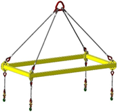
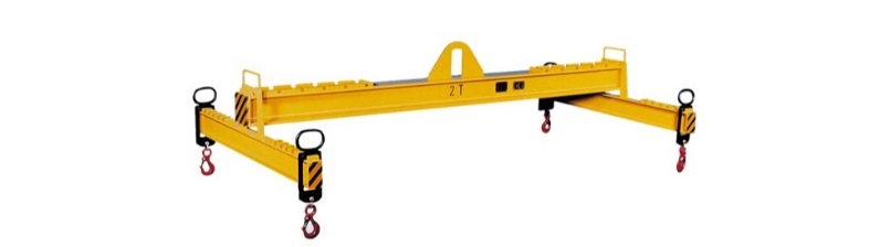
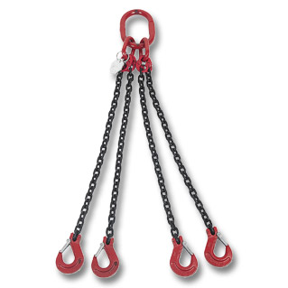
For lifting the chamber by crane/helicopter, suitable lifting accessories must be used, primarily lifting beams with hooks, spreader beams with hooks or chain slings with hooks.
The lifting machine may only be operated by a professionally qualified worker holding the relevant authorisation to operate the machine (crane operator/pilot).
Loads may only be attached and detached by a rigger holding the relevant authorisation for this activity – a rigger certificate.
To prevent the load from swinging or rotating during transport, a guide rope is used, which also enables precise positioning of the load.
ATTENTION: The rigger must ensure that the load is not transported above persons and must not remain under the load. The rigger must warn passing persons of the movement in good time.
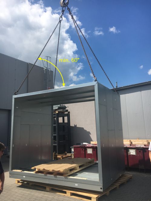
The minimum chain clamping angle relative to the upper edge of the chamber is 60°.
During handling, observe all applicable technical and legal regulations of the relevant country, e.g. ČSN EN 13 155+A2, ČSN ISO 12480-1.
ATTENTION: Only suitable and approved lifting accessories may be used for handling and transporting chambers!
Design:
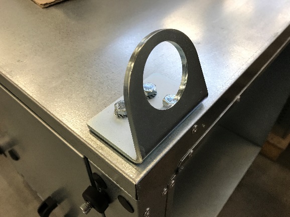
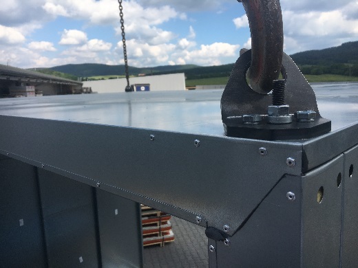
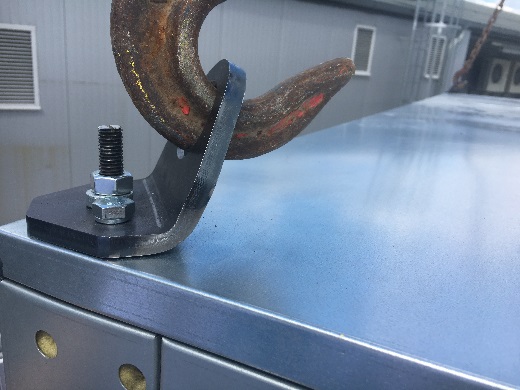
Lifting lugs type 1 “light-duty” are attached to the chamber roof, one lug using 4 M8 screws.
A size 13 wrench is required to loosen them.
Separate lifting lugs type 1 “light-duty” are only temporary elements and should be removed from the chambers after handling is completed.
In the case of an outdoor unit, after dismantling the lifting lugs it is necessary to assemble and install the unit roof on its top.
¶ 7. Handling a chamber using a crane/helicopter when suspended from lifting lugs – type 2 “heavy-duty” with higher load capacity
Limits of use:
Lifting lugs type 2 “heavy-duty” with higher load capacity are intended only for chambers with a maximum weight of 2700 kg, i.e. an evenly distributed load of 675 kg per lug. Chambers exceeding these limits must not be lifted using these lifting lugs.
These lugs can only be supplied for units with a base frame of at least 150 mm height.
These lugs can only be supplied for chambers with a maximum length of 4000 mm / maximum width of 4000 mm.
Attention! It is important not to confuse or interchange these lifting lugs type 2 “heavy-duty” with type 1 “light-duty” (see previous chapter), or with Profiles for ceiling attachment!
Profiles for ceiling attachment (L-profiles / Z-profiles) are used only for under-ceiling installation of units, are not intended for handling the chamber, and are intended only for the smallest units (up to size M5) with a maximum load capacity of 20 kg/profile, see chapter Assembly and installation
For lifting the chamber by crane/helicopter, suitable lifting accessories must be used, primarily lifting beams with hooks, spreader beams with hooks or chain slings with hooks.
The lifting machine may only be operated by a professionally qualified worker holding the relevant authorisation to operate the machine (crane operator/pilot).
Loads may only be attached and detached by a rigger holding the relevant authorisation for this activity – a rigger certificate.
To prevent the load from swinging or rotating during transport, a guide rope is used, which also enables precise positioning of the load.
ATTENTION: The rigger must ensure that the load is not transported above persons and must not remain under the load. The rigger must warn passing persons of the movement in good time.
The minimum chain clamping angle relative to the upper edge of the chamber is 60°.
During handling, observe all applicable technical and legal regulations of the relevant country, e.g. ČSN EN 13 155+A2, ČSN ISO 12480-1.
ATTENTION: Only suitable and approved lifting accessories may be used for handling and transporting chambers!
Design:
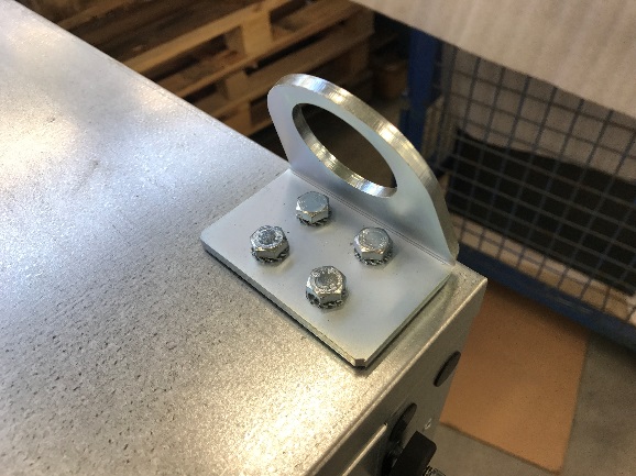
Lifting lugs type 2 “heavy-duty” are attached to the chamber roof, one lug using 2 M10 screws and one M10 threaded rod with two nuts – two size 17 wrenches are required to loosen them.
The two screws can be removed completely, but the threaded rod cannot. The threaded rod is provided with a slot for a screwdriver, by means of which the threaded rod can be screwed into the chamber casing. Make sure that the threaded rod is not screwed in too deeply so that it can be reused.
Separate lifting lugs type 2 “heavy-duty” are only temporary elements and should be removed from the chambers after handling is completed.
After removal, we recommend storing the lifting lugs together with the screws and nuts for later use.
In the case of an outdoor unit, after dismantling the lifting lugs it is necessary to assemble and install the unit roof on its top.
¶ 8. Handling a chamber using a crane/helicopter when suspended from lifting lugs – type 3 “frame-mounted”
Limits of use:
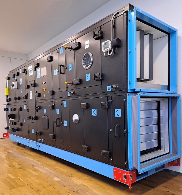
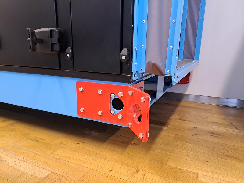
Lifting lugs type 3 “frame-mounted” are intended only for chambers with a maximum weight of 4000 kg, i.e. an evenly distributed load of 1000 kg per lug. Chambers exceeding these limits must not be lifted using these lifting lugs.
These lugs can only be supplied for units with a base frame of at least 150 mm height.
For lifting the chamber by crane/helicopter, suitable lifting accessories must be used, primarily lifting beams with hooks, spreader beams with hooks or chain slings with hooks.
The lifting machine may only be operated by a professionally qualified worker holding the relevant authorisation to operate the machine (crane operator/pilot).
Loads may only be attached and detached by a rigger holding the relevant authorisation for this activity – a rigger certificate.
To prevent the load from swinging or rotating during transport, a guide rope is used, which also enables precise positioning of the load.
ATTENTION: The rigger must ensure that the load is not transported above persons and must not remain under the load. The rigger must warn passing persons of the movement in good time.
The minimum chain clamping angle relative to the upper edge of the chamber is 60°.
During handling, observe all applicable technical and legal regulations of the relevant country, e.g. ČSN EN 13 155+A2, ČSN ISO 12480-1.
ATTENTION: Only suitable and approved lifting accessories may be used for handling and transporting chambers!
Design:
Lifting lugs type 3 “base-frame” are attached to the unit base frame, one lug using 12 M10 screws. Two size 17 wrenches are required to loosen them. The screws can be removed completely.
Separate lifting lugs type 3 “base-frame” are only temporary elements and should be removed from the chambers after handling is completed.
After removal, we recommend storing the lifting lugs together with the screws for later use.