¶ COMMISSIONING
¶ TASKS BEFORE THE FIRST START-UP
Before the first start-up, the following must be performed:
• Pre-start checks as per the previous section 6.
• Initial inspection of the electrical installation.
• Set the working point of the fans (speed or frequency) in accordance with the unit's technical specifications.
During the first start-up of the unit, the following must be monitored:
¶ TASKS DURING THE FIRST START-UP
 Fans must not be started with closed shut-off dampers in the unit or control dampers in the duct path. Pressure surges caused by tests of fire or other dampers with a short closing time should be avoided.
The first test start-up of the unit should not exceed 30 minutes. Afterwards, the unit and all its sections must be thoroughly re-inspected.
After the first commissioning, all intake filters must be cleaned or replaced with new ones if necessary.
During the first start-up, the following must be checked in particular:
Unit in general:
• Ensure no improper mechanical noises are heard.
• Check for excessive vibration of the unit.
• Tightness of the unit chamber and all additionally made penetrations through the unit casing.
• Fresh air (ODA) and exhaust air (EHA) dampers are open.
Water Heater:
• Check for tightness of the hydraulic system connection to the heat exchanger.
Electric Heater:
• The air velocity must not drop below 1 m/s.
Water Cooler:
• Check for tightness of the hydraulic system connection to the heat exchanger.
Direct Cooler:
• Check for tightness of the hydraulic system connection to the heat exchanger.
Plate Heat Exchanger:
• Ensure proper operation (opening) of the bypass damper according to the required performance of the heat recovery system.
• Proper operation of the condensate drain siphon (height, primed with water).
¶ FIRST COMMISSIONING OF THE UNIT
After completing all previous steps (installation, pre-start checks, etc.), the unit can be put into test operation:
- Connect the power supply – plug the power cable into the socket.
- Turn on the unit using the service switch – rotate it to position "1".
- Start the unit:
– See Appendix B. QUICK START OF THE UNIT - WEB/HMI CONTROLLER POL871.
– See Appendix C. QUICK START OF THE UNIT - CONTROLLER POL822. - Adjust the air performance – see section 8.4.
- Set the time program – refer to the manual:
"Detailed Manual for Operation and Commissioning of Climatix," available at: Control and Monitoring System in the Manuals and Other section, document MaR Climatix Operation Manual.
¶ AIRFLOW ADJUSTMENT OF THE UNIT
During the first start-up and after completing the tasks from the previous section 8.3, the airflow of the unit must be checked according to the specifications, and, if necessary, the speed of the EC fans should be adjusted.
Quick setup of the supply/exhaust fan performance is provided in Appendix A. QUICK FAN PERFORMANCE SETUP - WEB/HMI CONTROLLER POL871.
Commissioning the unit (operating mode) is provided in Appendix B. QUICK START OF THE UNIT - HMI CONTROLLER POL871.
or
Commissioning the unit (operating mode) is provided in Appendix C. QUICK START OF THE UNIT - CONTROLLER POL822.
For airflow measurement of the fan, or its differential pressure, the unit is equipped with measurement probes, as shown in the following image.
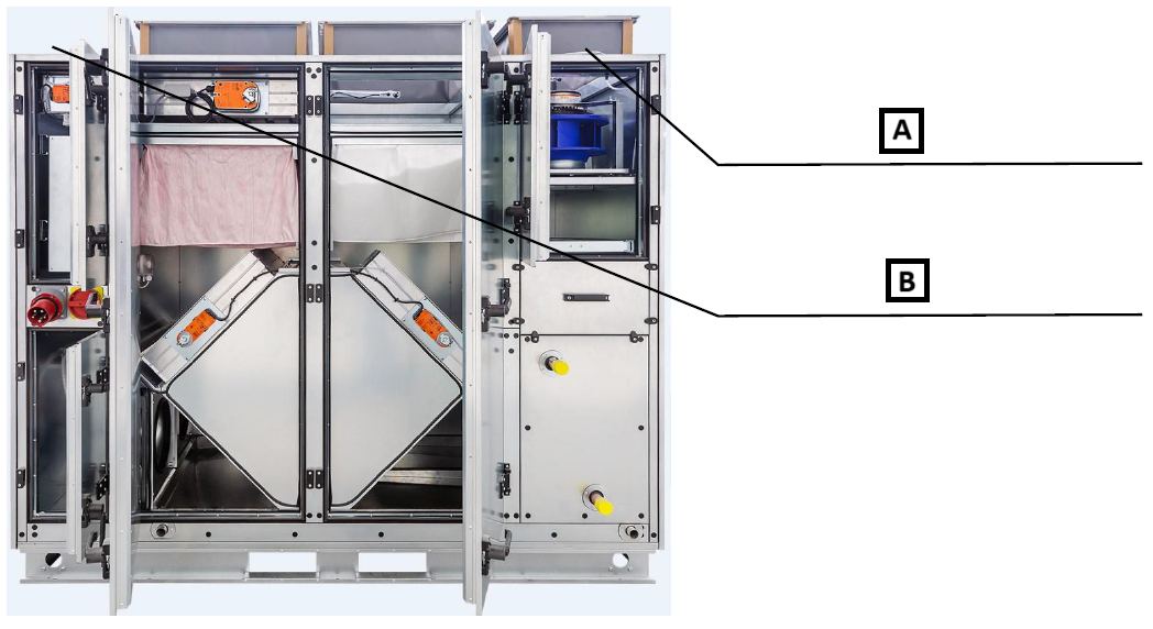
A: Supply fan probe for differential pressure measurement.
B: Exhaust fan probe for differential pressure measurement.
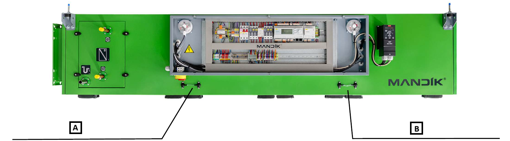
A: Supply fan probe for differential pressure measurement.
B: Exhaust fan probe for differential pressure measurement.
After measuring the differential pressure [Pa], the airflow is calculated based on the k-factor of the fan and the formula indicated on the fan label. Alternatively, the airflow can be calculated as follows:
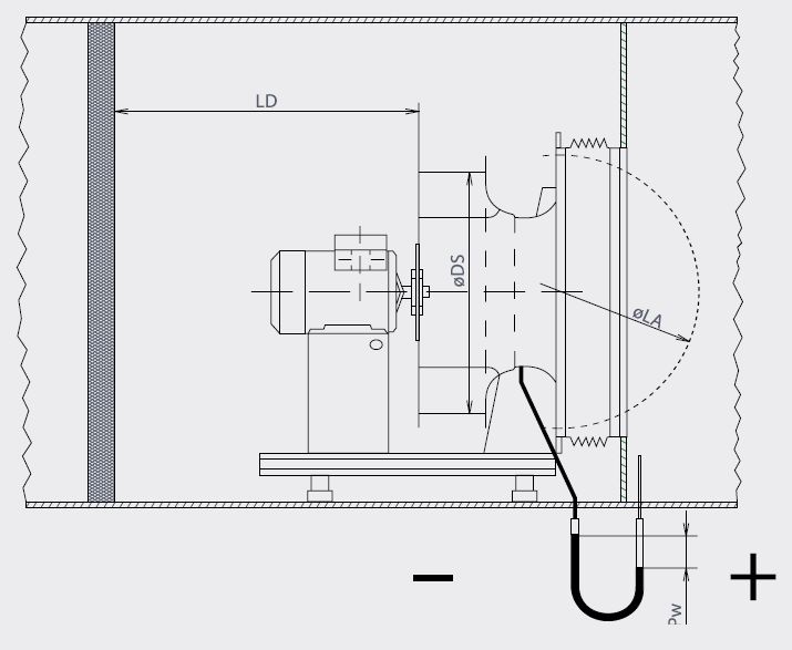
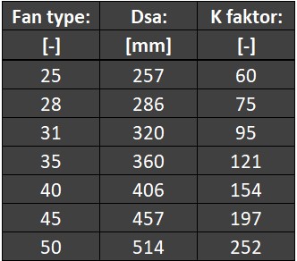
Formula for calculating airflow .
k = k-factor (table above), = measured pressure difference [Pa].
To eliminate any deviation between the measured and the required airflow (as per the project or technical specification), the fan speed is adjusted by changing the fan's power output [%]. Increasing power = increasing airflow, and vice versa.
During the adjustment process, all dampers must be in the fully open position.
If the required airflow cannot be achieved, this indicates a need to check the unit (internal blockage, foreign pressure losses) or the ductwork (foreign pressure losses, designed external pressure drop not matching the actual ductwork installation), etc.
A record of the airflow adjustment must be documented in the relevant protocol.
The measured values are satisfactory if the deviation between the measured values and those specified in the technical documentation does not exceed ±10%.
It is always necessary to perform airflow adjustment based on the pressure ratios defined by the project or the type of operation of the air-conditioned space – isobaric/overpressure/underpressure ventilation.
The adjustment protocol must include the following information:
• Equipment identification (order number, serial number, project position).
• Details of the person performing the adjustment, including signature or stamp.
• Equipment nominal parameters (airflows, fan motor current loads – nameplate values).
• Measuring instruments used.
• Functional diagram of the equipment, including a schematic of the ductwork with dimensions and descriptions of its components (inserted elements – attenuators, filters, etc., control dampers, branches, bends, etc.).
• List and values of measurement points.
• Timeline of the adjustment process (unit start-up, unit shutdown).
• Climatic conditions during equipment operation (inlet/outlet temperatures and humidities of the supplied and exhausted air).
• Record of the operation and condition of individual parts of the unit listed in section 7.1.
• Record of detected faults.
• Record of test evaluation (result, date, etc.).
• Table of measured and set values for each fan (airflows, currents, etc.).
¶ TRAINING OF OPERATORS AND HANDING OVER THE UNIT
During training, the following steps must be followed:
• Train the user on the operation and maintenance of the unit.
• Record the training session. A copy will be sent to MANDÍK, a.s. or the service department's email service@mandik.cz.
• Train the user on the operation and adjustment of user parameters of the Climatix control system.
• Record the Climatix system training session. A copy will be sent to MANDÍK, a.s. or the service department's email service@mandik.cz.
• Record the unit's airflow adjustment. A copy will be sent to MANDÍK, a.s. or the service department's email service@mandik.cz.
• Hand over the unit to the user.
• Record the handover of the unit to the user. A copy will be sent to MANDÍK, a.s. or the service department's email service@mandik.cz.
• Create an operation logbook for the equipment.
• Hand over the documentation to the user (manufacturer's manuals, electrical installation inspection, training protocol for operation and maintenance, MaR system training protocol, unit handover protocol, airflow adjustment protocol).
¶ OPERATION AND MAINTENANCE
¶ UNIT DESCRIPTION – COMPONENTS
A: SHUT-OFF DAMPER - EHA
B: ACCESS TO THE DISTRIBUTION BOARD
C: MAIN SUPPLY
D: MAIN SWITCH
E: SHUT-OFF DAMPER - ODA
F: INLET FILTER
G: OUTLET FILTER
H: FAN - INLET
I: BYPASS DAMPER
J: BYPASS ZZT
K: MIXING DAMPER
L: EXCHANGER NO. 2 (HEATING)
M: EXCHANGER NO. 1 (HEATING/COOLING)
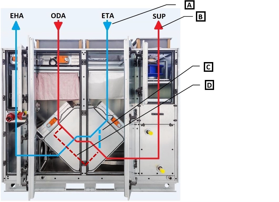
A: ETA = exhaust from space
B: SUP = supply to space
C: mixing of exhaust air with supply air
D: fresh air bypass
¶ UNIT DESCRIPTION – MaR SYSTEM
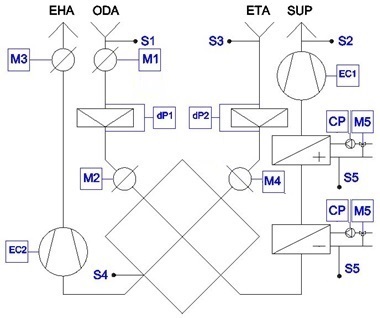
EC1/EC2 – inlet/outlet EC fan
M1 – actuator for inlet damper
M2 – actuator for bypass damper
M3 – actuator for outlet damper
M4 – actuator for mixing damper
M5 – actuator for 3-way mixing valve (heater/cooler)
dP1 – differential pressure switch (inlet filter)
dP2 – differential pressure switch (outlet filter)
S1 – temperature sensor for fresh air
S2 – temperature sensor for supply air
S3 – temperature sensor for exhaust air
S4 – temperature sensor for frost protection (ZZT heat recovery unit)
S5 – temperature sensor for return water (heater/cooler)
CP – circulation pump (heater/cooler)
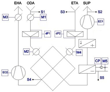
EC1/EC2 – inlet/outlet EC fan
M1 – actuator for inlet damper
M2 – actuator for bypass damper
M3 – actuator for outlet damper
M4 – actuator for mixing damper
M5 – actuator for 3-way mixing valve (cooler)
dP1 – differential pressure switch (inlet filter)
dP2 – differential pressure switch (outlet filter)
S1 – temperature sensor for fresh air
S2 – temperature sensor for supply air
S3 – temperature sensor for exhaust air
S4 – temperature sensor for frost protection (ZZT heat recovery unit)
S5 – temperature sensor for return water (cooler)
CP – circulation pump (cooler)
¶ OPERATION AND MAINTENANCE GENERAL
The following prescribed maintenance and service intervals for individual parts of the unit must be followed to maintain the manufacturer's warranty from MANDÍK, a.s., and to ensure safe and trouble-free operation of the unit.
These intervals are intended for standard units with normal operating conditions. For units operated differently (24-hour operation, higher working temperatures, increased air dustiness, etc.), maintenance and service intervals must be shortened by at least one level. The specific intervals depend on the operating conditions established during commissioning, training, and handover of the unit.
All maintenance operations, revisions, and inspections must be recorded in the unit's operation log. The obligation to establish and maintain the operation log belongs to the person commissioning the unit. Entries about individual events are made by the unit operator.
 SAFETY DURING MAINTENANCE:
• WARNING: ALL WORK, MAINTENANCE, AND INTERVENTIONS ON THE UNIT MUST BE CARRIED OUT ONLY BY QUALIFIED PERSONS WITH THE APPROPRIATE AUTHORIZATIONS (E.G., GAS INSTALLATIONS, ELECTRICAL INSTALLATIONS, ETC.)!
• WARNING: SERVICE WORK AND MAINTENANCE ON THE UNIT MAY ONLY BE CARRIED OUT WITH THE UNIT SWITCHED OFF (IT MUST BE SECURED AGAINST SPONTANEOUS STARTING OR STARTING BY ANOTHER PERSON)!
• WARNING: BEFORE ENTERING THE UNIT, ALL ROTATING PARTS (FANS, ETC.) MUST BE IN A STATIONARY STATE!
• WARNING: ELECTRIC HEATERS, HEAT EXCHANGERS, AND PARTS OF THE HYDRAULIC SYSTEM MUST BE COOLED TO AMBIENT TEMPERATURE; THE MAXIMUM SURFACE TEMPERATURE IS +40°C!
• WARNING: THE PRESSURE IN THE PRESSURIZED SYSTEMS MUST BE EQUALIZED TO AMBIENT PRESSURE!
¶ SERVICE AND MAINTENANCE INTERVALS
Detailed operating instructions and maintenance and service procedures are provided in sections 9.5 and beyond for individual unit parts.
| SERVICE AND MAINTENANCE TASKS | | | | ||||||
|---|---|---|---|---|---|---|---|---|
| | Inspection task | Unit in operation Y/N* | Method of service/removal | Intervals (months) ||||||
| 9. End dampers | | | | |1|3|6|12|
| 9.01. | Check the free movement of dampers. | N | repair/replacement ||||✓||
| 9.02. | Check for damper contamination. | N | cleaning ||||✓||
*Unit operating status during the inspection
¶ GENERAL UNIT OPERATION AND MAINTENANCE
All persons performing maintenance on air conditioning units must be familiar with the content of maintenance instructions and follow the recommendations given therein. These instructions are supplementary and assume knowledge of the installation and operating instructions for MANDÍK, a.s. air conditioning units of the CPV series and compliance with all requirements contained therein. The manufacturer accepts no liability for any damage caused by non-compliance with installation and operating instructions and these instructions.
Air conditioning units are machines for air transport and treatment that require regular maintenance and cleaning. Depending on the scope and purpose of the air handling system they are part of, and the composition and equipment of the air conditioning unit itself, we recommend that the operator develop a local operating and maintenance manual that respects the requirements of the installation and operating instructions and the maintenance instructions for MANDÍK, a.s. CPV series air conditioning units.
All maintenance intervals mentioned in the text are indicative and valid for air containing a normal amount of pollutants. These intervals can be extended or shortened depending on local operating conditions, the nature of the equipment, and the level of air contamination. These intervals also do not absolve the operator of the responsibility to ensure daily trouble-free and safe operation of the air conditioning unit.
All elements that are intended to be pulled out, opened, or easily dismantled must be positioned in a way that allows the most thorough cleaning of the interior of the unit. Coarse dirt is removed with a vacuum cleaner; if necessary, a damp cloth is used. For greasy dirt, neutral cleaning agents are used, and then the surface is wiped with a damp cloth again. Any damage to painted surfaces or traces of corrosion must be treated and repaired with a suitable coating. Movable parts (hinges, handles, etc.) should be treated with a lubricating spray as needed. All inspection doors must be properly seated, and it must be checked that they open freely. Depending on the unit's installation conditions, it may be necessary to readjust the doors using the adjustment allowances on the bolts of the handles and hinges. The correct sealing of the doors must be checked. If leakage is detected, repair or replace the seal.
¶ FANS
Before starting any interventions or work on the fans, wait for the fan impeller to come to a complete stop. Additionally, spontaneous starting or accidental starting of the fan by another person must be prevented! This is ensured by the safety switch on the front or side of the unit (depending on the specific unit configuration).
For the fan, check the cleanliness of the free impeller, remove any coarse dust with a vacuum cleaner, and wipe fine dust with a damp cloth.
Keeping the fan impeller clean is crucial, especially to maintain the best possible balance. Any damage to painted surfaces or traces of corrosion must be treated and repaired with a suitable coating.
Regularly check for imbalance (vibrations), the attachment of the impeller to the hub, and the hub to the motor shaft. Also, check the clearance between the free impeller and the fan's inlet and tighten all screw connections on the motor and fan assembly. For the electric motor, check for vibrations, bearing noise, possible overheating, the tightness of terminal connections in the terminal box, and the integrity of the grounding connection to the chamber frame.
During maintenance, measure the motor current, check the voltage, and phase symmetry. Repair any surface damage. Check the proper attachment of the electric motor to the base and all screw connections on the fan assembly's base.
¶ FILTERS
Dust deposited on the filter element can cause allergic reactions on the skin, mucous membranes, and eyes or respiratory problems. Therefore, avoid contact with trapped dust. When maintaining and replacing filter elements, wear protective clothing and, if necessary, protective equipment (respirator, etc.)!
For the filter section, check the cleanliness; remove any coarse dust with a vacuum cleaner, and wipe fine dust with a damp cloth. Also, check for clogging and leaks in the entire