¶ APPENDIX B. INSTALLATION OF SPLIT VERTICAL RECUPERATION
This design of the recuperation chamber is intended for units with an air flow greater than 20,000 [m3/h]. The division of the recuperation chamber facilitates transport and installation.
A: Wall
B: Upper part of the chamber
C: Bypass cover
D: Cover
E: Plate recuperator
F: 8 x guide rail
G: Bypass cover
H: Lower part of the chamber
I: Wall
J: Cover
K: Assembled recuperation chamber
L: Operating side
M: Service panels
¶ B.1 Handling
Delivery components
-
Lower part of the recuperation chamber
-
Upper part of the recuperation chamber
-
Plate recuperator
-
All loads are equipped with handling points, see Figure 2
-
The lower and upper parts of the chamber are completely fitted with flaps, eliminators, holders, etc.
-
Couplings, fasteners
-
Standard accessories needed for assembling the recuperation chamber (described in the KJM MANDÍK document
Installation, Commissioning and Maintenance)Not included in the delivery
-
Crane with appropriate load capacity
-
Crane and binding equipment such as eyes, hooks, chains, textile straps
-
Assembly tools
-
Handling beam with clamping points, see Figure 3
Recommended design of the handling beam
- Beam length = at least the length of the chamber
Load capacity of the beam corresponding to the weight of the heaviest load
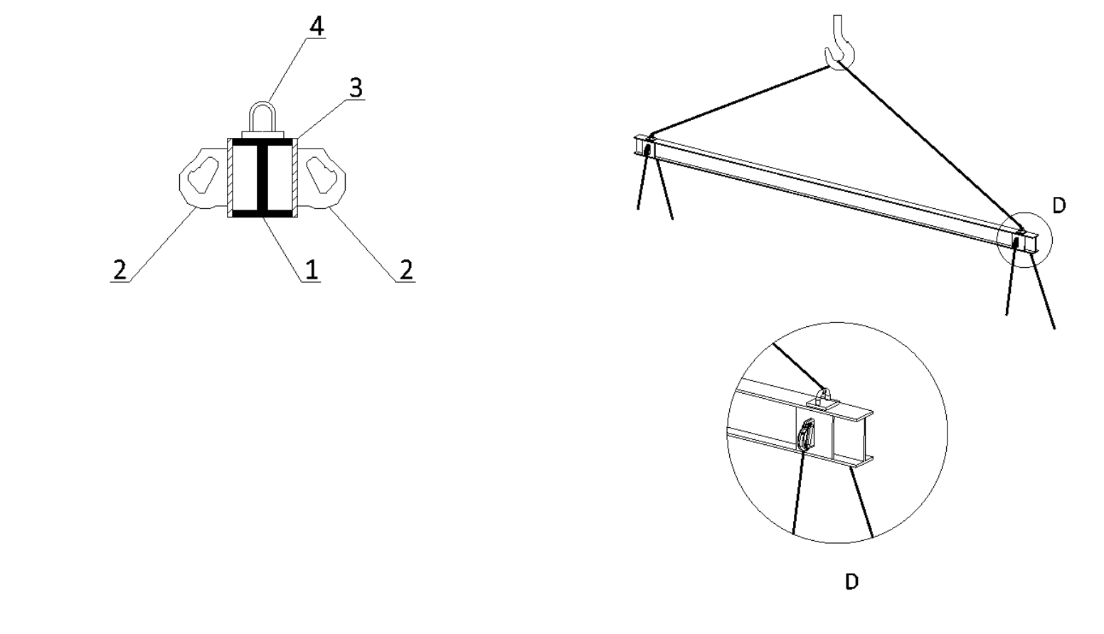
1: Profile I
2: Welding eye
3: Flat bar
4: Welding eye
D: Detail D
¶ B.2 Installation of the lower part of the chamber at the designated location
-
Use the holes in the base frame to secure the binding medium, see Figure 2, Detail C
-
Clamp the binding medium to the handling beam, see Figure 3
-
Attach the crane hook to the handling beam, see Figure 3
-
Move the lower part of the chamber to the prepared substrate (described in the KJM MANDÍK document Installation, Commissioning and Maintenance, Chapter 5.6 General Unit Assembly)
-
Length of the handling beam = min. length of the chamber

Do not remain under the load during handling - there is a risk of fatal injury due to falling loads!
Do not pass textile straps through the holes in the base frame - there is a risk of cutting the fabric, resulting in the load falling!
Example of the recommended clamping of the lower part of the chamber through the holes in the base frame using the handling beam:
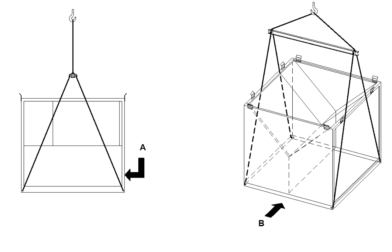
A: Operating side.
B: Operating side.
¶ B.3 Clamping the plate recuperator
- Use the handling points for clamping the plate recuperator, see Figure 2, Detail A
- Recommended clamping methods for the plate recuperator, see Figure 5
Do not pass textile straps through the clamping points - there is a risk of cutting the fabric!
Example of correct clamping of the plate recuperator:
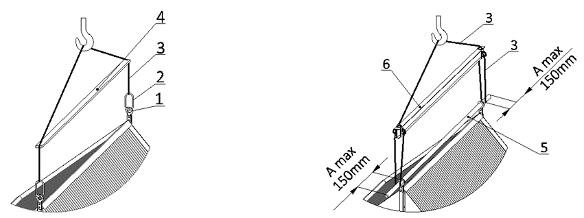
A: Example No. 1, left: Use of eyes, binding equipment, spacers.
B: Example No. 2 clamping, right: Use of pipe, handling beam, and binding equipment.
For example No. 2, right: Recommended dimensions for the handling pipe
-Maximum overhang of pipe A max = 150mm, see Figure 6
-Pipe diameter 60-69mm
-Minimum wall thickness of the pipe 4mm
Overall description:
1: Handling points of the recuperator
2: Eye
3: Binding medium
4: Spacer
5: Pipe
6: Handling beam
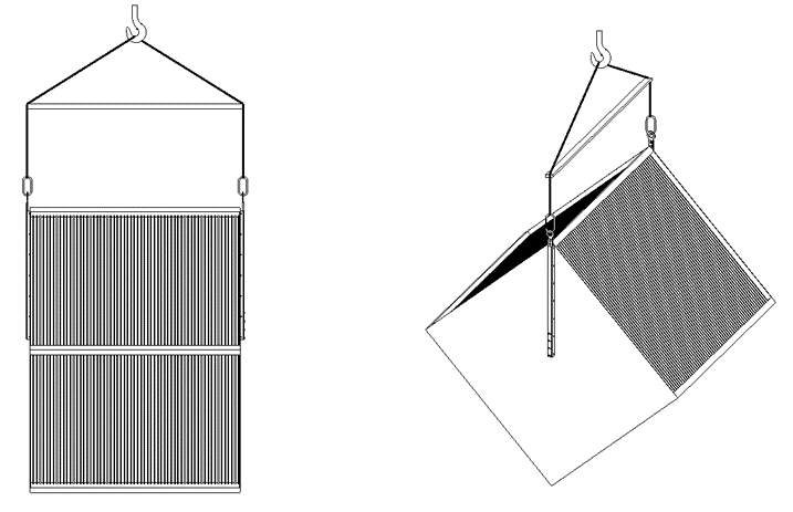
Suspension of the plate recuperator - handling position:
¶ B.4 Installation of the non-split plate recuperator into the lower part of the chamber
-
Both the lower and upper parts of the chamber are equipped with seals, see Figure 7
-
Install the recuperator on the prepared seal, see Figure 8
-
Correct position of the recuperator - maximum distance of the front surface of the recuperator’s suspension, see Figure 9, Detail E
When positioning the recuperator, always lift it sufficiently so as not to damage the installed seal.
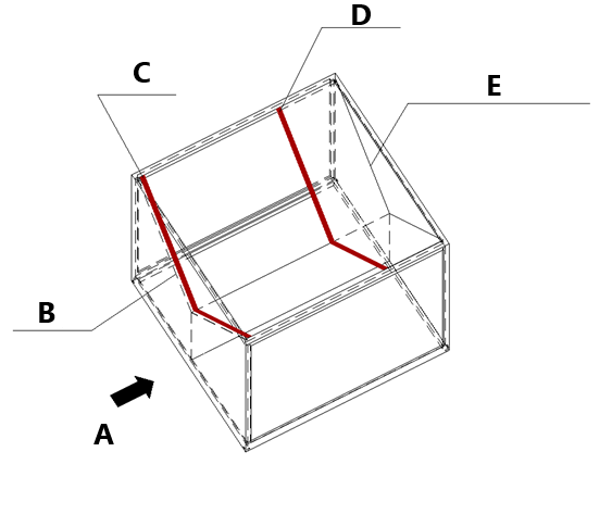
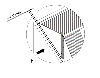
Figure 7, left: Seal placement
A: operating side
B: cover
C: seal
D: seal
E: bypass cover
F: operating side
Detail E, right: Position of the recuperator relative to the chamber
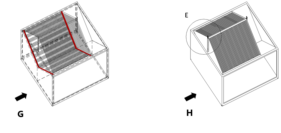
Figure 8, left: Positioning of the recuperator
Figure 9, right: Positioning of the recuperator
G: operating side
H: operating side
¶ B.5 Disassembly of the rods with crane eyes -- non-split heat exchanger
After the proper positioning of the recuperator, disassemble 8 pcs of M8 screws on each side, see Figure 10, Detail F, G.
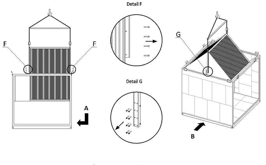
A: operating side
B: operating side
After disassembling the screws, lift the rods out of the recuperator's bushings, see Figure 11:
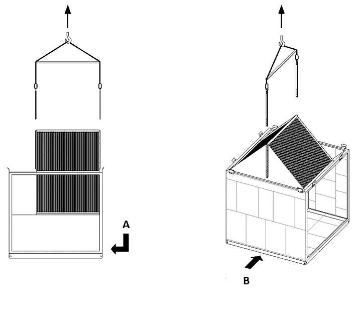
A: Operating side
B: Operating side
¶ B.6 Installation of the split plate recuperator into the lower part
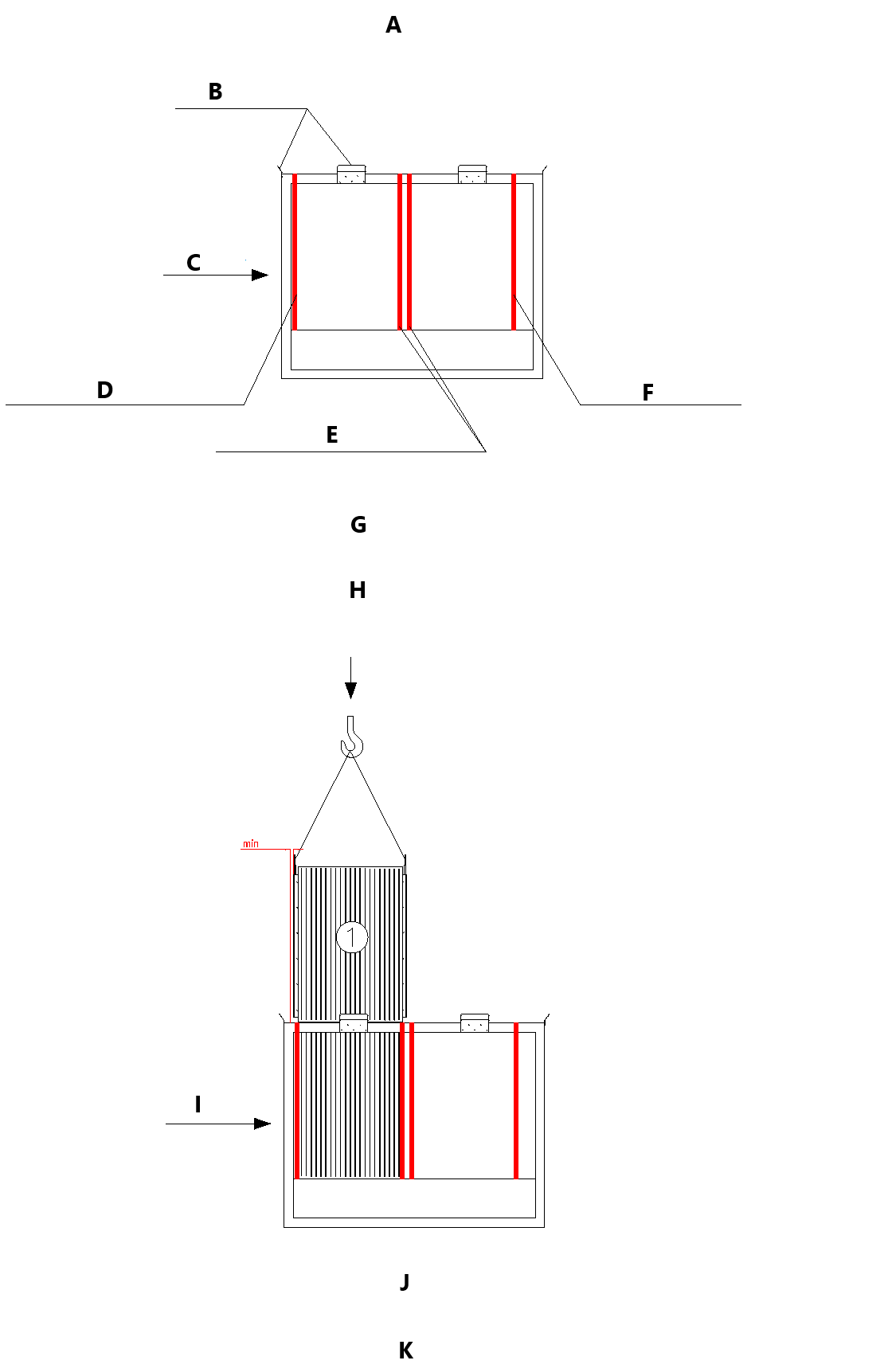
A: Installation of the split plate recuperator into the lower part of the chamber.
B: guide rails
C: operating side
D: seal - front cover rail
E: seal - middle cover rail
F: seal - bypass
G: Sealing sheets are fitted at both the bottom and top of the chamber; the guide sheets placed on the lower chamber serve for precise and unambiguous positioning of the upper part of the chamber. After placing the upper part onto the lower and subsequently connecting them with the eccentric, the guide sheets from the lower part are removed - see further in the assembly procedure.
H: Description of the chamber - sealing rails, guide sheets.
I: operating side
J: Install recuperator 1 as close to the front wall (operating side) as possible. The recuperator must sit on the prepared seal located on the cover rails. The tightness between the recuperators and the cover rails of both the upper and lower parts of the chamber will be ensured in the final step of the chamber assembly using self-tapping screws - see further in the procedure.
K: Figure Handling of plate recuperator 1
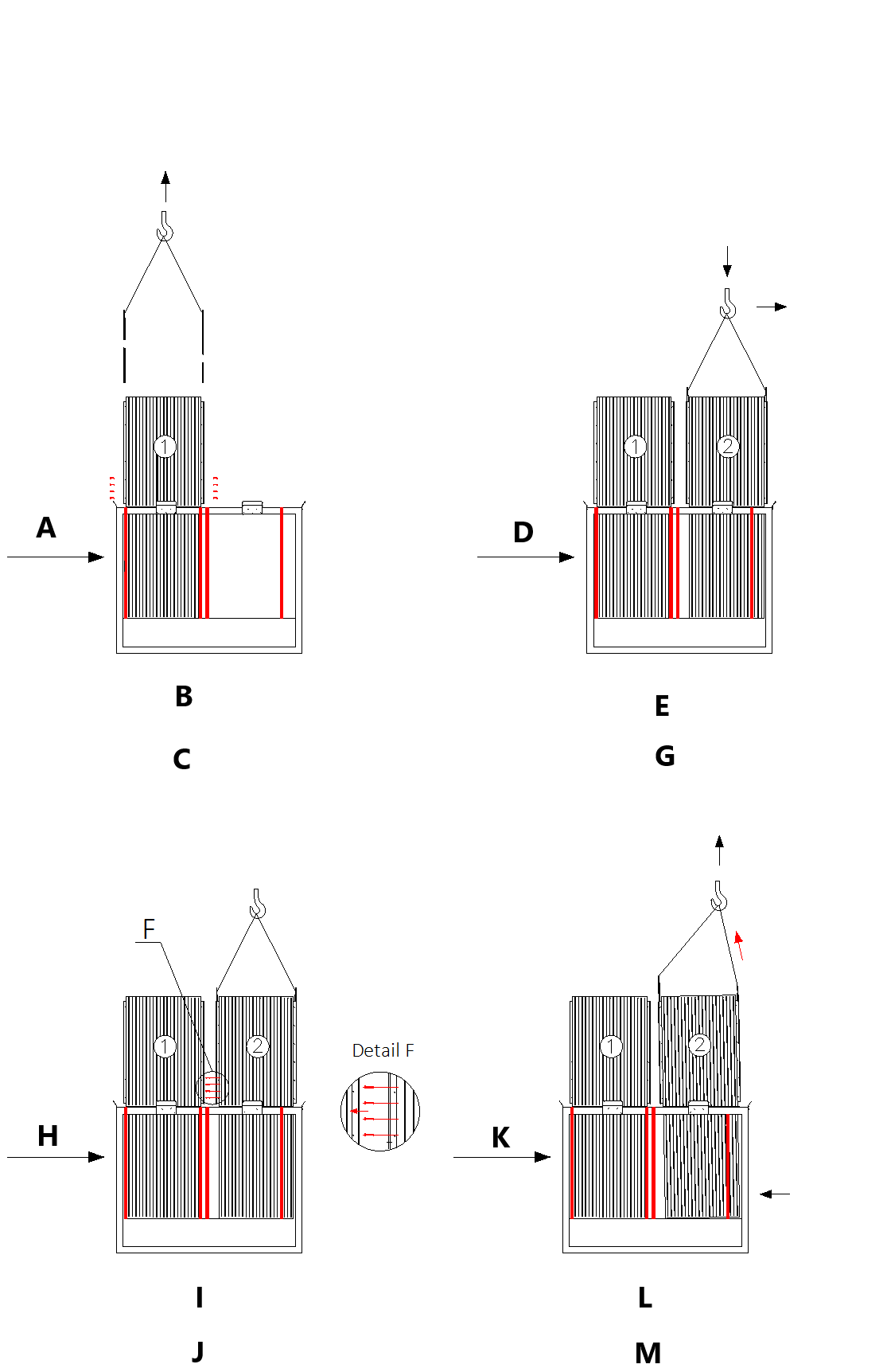
A: operating side
B: After placing the recuperator, remove the screws from both suspensions and pull the suspensions out of the bushings.
C: Figure Unlocking of the suspensions of recuperator 1.
D: operating side
E: Place recuperator 2 as close to the back wall of the chamber as possible, thus leaving as much assembly space as possible between both recuperators.
G: Figure Handling of plate recuperator 2.
H: operating side
I: Disassemble the screws of the internal suspension of recuperator 2, see detail F.
J: Figure Disassembly of the screw of the internal suspension.
K: operating side.
L: The internal suspension is already unlocked; only the external suspension of recuperator 2 is in place. Lift recuperator 2 approximately 1 cm and manually push it against the front recuperator 1.
M: Figure Handling of recuperator 2.
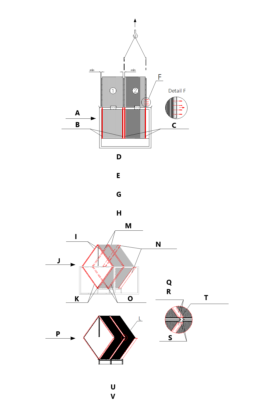
A: operating side
B: recuperator seal after lifting up
C: Remove screws from both suspensions and remove them from the bushings.
D: Disassemble the last suspension of recuperator 2.
E: It is important to lift both recuperators in such a way that there is sufficient space to ensure that the seals fit perfectly against the chamber wall. The detailed placement of the recuperators is demonstrated in Figures 8 and 9.
¶ B.7 Removal of the cover of the lower part of the chamber
-
The cover must be prepared for installation before the upper part of the chamber can be installed.
-
Remove screws, see Figure 10.
-
Ensure that the seals are properly positioned on the cover, see Figure 12.
-
Carefully position the cover on the lower part of the chamber; the seals must fit together.
-
If the upper part of the chamber has already been prepared, proceed with the next step.
-
After placing the cover, tighten the screws to ensure tightness.
-
Follow the procedures in the KJM MANDÍK document Installation, Commissioning and Maintenance.
¶ B.8 Installation of the upper part of the chamber
-
The upper part of the recuperator chamber is prepared for installation; ensure that the seals are properly positioned on the frame, see Figure 12.
-
Use the handling beam with a suitable load capacity.
-
Secure the binding medium through the eyelets of the upper part of the chamber.
-
After lifting the upper part of the chamber, move it to the appropriate position over the lower part.
-
Carefully lower the upper part onto the lower part, ensuring that the seals fit properly.
-
Tighten all screws, including the cover screws.
-
Follow the procedures in the KJM MANDÍK document Installation, Commissioning and Maintenance.