TPM 176/25 - rev.1 - Valid from 1 December 2025
¶ CPX MANDÍK COMPACT CEILING-MOUNTED AIR HANDLING UNITS
The CPX range of compact air handling units is designed for central air distribution and treatment in commercial and industrial applications. The units are designed for ceiling mounting, with the connections oriented horizontally according to the available installation space.
Thanks to advanced software and a well-engineered design, the units can be configured dynamically. This enables a unique design of both standard and non-standard units according to the specific requirements, including any dimensional constraints. A wide range of internal components and their combinations is available. The units are fully manufactured and certified in a frameless design and are intended for indoor installation.
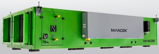
The standard configuration includes a counterflow plate heat recovery exchanger, the option to equip the unit with one or two heat exchangers for heating and cooling, selection of any fan types according to price, efficiency and design preferences, an optional mixing/recirculation function for extract air, a choice of circular or rectangular connections, the choice of an externally mounted integrated electrical switchboard or a switchboard supplied with free-length cables for wall mounting, and other optional features.
The CPX units are designed for airflows from 500 to 4,500 m³/h and are supplied as plug&play as standard, i.e. including an integrated measurement and regulation system.
¶ 1. GENERAL INFORMATION
¶ 2. RELATED DOCUMENTS
¶ 2.1. COMMON DOCUMENTS
¶ 2.2. CPX-SPECIFIC DOCUMENTS
¶ 3. UNIT IDENTIFICATION
¶ 3.1. MACHINE IDENTIFICATION AND NAMEPLATE
3.1. MACHINE IDENTIFICATION AND NAMEPLATE
¶ 3.2. UNIT DIMENSIONS
The dimensions of each unit are determined dynamically in 1 mm increments. The dimensions are calculated automatically by the software according to the specific requirements.
The exact dimensions of the selected unit are stated in the relevant technical specification or on the identification label.
The maximum manufacturing dimensions (measured to the outer casing) are: length × width × height = 3880 × 2000 × 1000 mm.
¶ 3.3. CONNECTION DIMENSIONS
Depending on the specification, the unit may be fitted with rectangular or circular air connections.
The dimensions of the air connections are calculated dynamically by the software according to the specific requirements in 10 mm increments.
The exact connection dimensions of the selected unit are stated in the relevant technical specification.
¶ 4. SAFETY
The unit must be installed in an area with controlled access.
¶ 4.1. COMPLIANCE WITH LEGAL REQUIREMENTS AND STANDARDS
4.1. COMPLIANCE WITH LEGAL REQUIREMENTS AND STANDARDS
¶ 4.2. GENERAL SAFETY INSTRUCTIONS
4.2. GENERAL SAFETY INSTRUCTIONS
¶ 4.3. NOISE EMISSIONS AT THE OPERATOR'S POSITION
4.3. NOISE EMISSIONS AT THE OPERATOR'S POSITION
¶ 5. HANDLING, TRANSPORT AND STORAGE
5. HANDLING, TRANSPORT AND STORAGE
¶ 6. ASSEMBLY AND INSTALLATION
¶ 6.1. GENERAL
¶ 6.2. UNIT SUSPENSION
¶ 6.3. UNIT DESCRIPTION – COMPONENT LAYOUT, AIRFLOW, MEASUREMENT AND REGULATION SYSTEM
6.3. UNIT DESCRIPTION – COMPONENT LAYOUT, AIRFLOW, MEASUREMENT AND REGULATION SYSTEM
¶ 6.4. UNIT ASSEMBLY
¶ 6.5. MAIN ELECTRICAL SWITCH AND DISCONNECTION OF THE UNIT FROM THE POWER SUPPLY
6.5. MAIN ELECTRICAL SWITCH AND DISCONNECTION OF THE UNIT FROM THE POWER SUPPLY
¶ 7. COMMISSIONING
¶ 7.1. ACTIVITIES PRIOR TO COMMISSIONING – GENERAL
7.1. ACTIVITIES PRIOR TO COMMISSIONING – GENERAL
¶ 7.2. COMMISSIONING ACTIVITIES
¶ 7.3. OPERATOR TRAINING AND UNIT HANDOVER
7.3. OPERATOR TRAINING AND UNIT HANDOVER
¶ 7.4. CONDITIONS FOR COMMISSIONING
7.4. CONDITIONS FOR COMMISSIONING
¶ 8. OPERATION AND MAINTENANCE
¶ 8.1. COMMON INSTRUCTIONS
¶ 8.2. COMMON MAINTENANCE INTERVALS
8.2. COMMON MAINTENANCE INTERVALS
¶ 9. INDIVIDUAL BUILT-IN COMPONENTS – DESCRIPTION, ASSEMBLY AND INSTALLATION, COMMISSIONING, OPERATION AND MAINTENANCE
¶ 9.1. FAN SECTION
¶ 9.2. FILTER SECTION
¶ 9.3. PLATE HEAT EXCHANGER SECTION
9.3. PLATE HEAT EXCHANGER SECTION
¶ 9.4. WATER, CONDENSER AND STEAM HEATER SECTION
9.4. WATER, CONDENSER AND STEAM HEATER SECTION
¶ 9.5. ELECTRIC HEATER SECTION
¶ 9.6. WATER COOLER SECTION
¶ 9.7. DIRECT-EXPANSION COOLER SECTION
9.7. DIRECT-EXPANSION COOLER SECTION
¶ 9.8. END WALL AND DAMPER SECTION – GENERAL
9.8. END WALL AND DAMPER SECTION – GENERAL